Table of Contents
Advertisement
Quick Links
Download this manual
See also:
Operating Manual
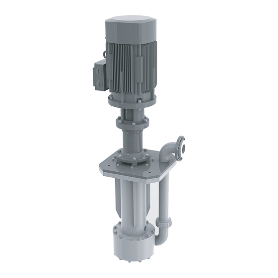
Plastic
Sump Pump
Original operating manual
Version
BA-2018.08.22 EN
Print-No.
300 106
TR MA DE Rev003
Series ETL
STÜBBE GmbH & Co. KG
Hollwieser Straße 5
32602 Vlotho
Germany
Phone: +49 (0) 5733-799-0
Fax: +49 (0) 5733-799-5000
E-mail:
contact@stuebbe.com
Internet:
www.stuebbe.com
Subject to technical modifications.
Read carefully before use.
Save for future use.
Advertisement
Table of Contents
Troubleshooting

Related Manuals for Stübbe ETL series


Summary of Contents for Stübbe ETL series
- Page 1 Plastic Sump Pump Original operating manual Series ETL Version BA-2018.08.22 EN STÜBBE GmbH & Co. KG Print-No. 300 106 Hollwieser Straße 5 32602 Vlotho TR MA DE Rev003 Germany Phone: +49 (0) 5733-799-0 Fax: +49 (0) 5733-799-5000 E-mail: contact@stuebbe.com Internet: www.stuebbe.com Subject to technical modifications.
-
Page 2: Table Of Contents
Table of contents Table of contents ....... 4 6.1.1 Check downtimes . - Page 3 Table of contents List of figures List of tables Fig. 1 Name plate (example) ..... . . 8 Tab. 1 Other application documents, purpose and where found .
-
Page 4: About This Document
About this document About this document Other applicable documents This manual: • is part of the equipment • applies to all series referred to Document/purpose/ Where found • describes safe and proper operation during all operating Installation drawing Documentation phases included •... -
Page 5: Warnings And Symbols
About this document Warnings and symbols Symbol Meaning • Immediate acute risk • Death, serious bodily harm • Potentially acute risk • Death, serious bodily harm • Potentially hazardous situation • Minor injury • Potentially hazardous situation • Material damage Safety warning sign Take note of all information highlighted by the safety warning... -
Page 6: Safety
Safety Safety The manufacturer accepts no liability for damage caused • The type of installation should be selected only in accor- by disregarding any of the documentation. dance with these operating instructions. For example, the following are not allowed: – Hanging base plate pumps in the pipe –... -
Page 7: Obligations Of Personnel
Safety • Following all work on the pump, refit safety devices in Qualified personnel accordance with the instructions and bring into service. • Make sure all personnel tasked with work on the pump have read and understood this manual and all other appli- •... -
Page 8: Layout And Function
Layout and function Layout and function Marking Assembly 3.1.1 Name plate Hollwieser Str. 5 D-32602 Vlotho Typ: Ser. NO.: ID. NO.: Mat.: M. Seal: Imp. Ø: /h H: Fig. 1 Name plate (example) Pump type Serial number Ident. number Housing / sealing material Shaft seal information Impeller diameter [mm] Differential head... -
Page 9: Transport, Storage And Disposal
Transport, storage and disposal Transport, storage and disposal Transport 4.1.2 Lifting The user/owner is responsible for the transport of the DANGER pump. Death or limbs crushed as a result transported items Weight specifications (→ documents for the particular falling over! order) Use lifting gear appropriate for the total weight to be trans- ported. -
Page 10: Storage
Transport, storage and disposal Storage DANGER Death or limbs crushed as a result of the pump overturn- ing! For vertical storage: – Place pump on a horizontal underground and secure against overturning. NOTE Material damage due to inappropriate storage! Store the pump properly. 1. -
Page 11: Setup And Connection
Setup and connection Setup and connection NOTE 5.1.3 Surface preparation Aids, tools, materials: Material damage due to distortion or passage of electrical – Spirit level current in the bearing! 1. Make sure the surface meets the following conditions: Do not make any structural modifications to the pump –... -
Page 12: Specifying Nominal Widths
Setup and connection Connecting the pipes 5.3.2 Specifying nominal widths Keep the flow resistance in the pipes as low as possible. NOTE 1. Make sure the suction extension is not smaller than the Material damage due to excessive forces and torques on nominal width of the suction branch. -
Page 13: Electrical Connection
Setup and connection Electrical connection DANGER Risk of electrocution! All electrical work must be carried out only by qualified elec- tricians. Before all work on the electrical system, disconnect the motor from the mains and secure against being switched back on again. 5.5.1 Connecting the motor Follow the instructions of the motor manufacturer. -
Page 14: Operation
Operation Operation Preparing for commissioning NOTE Risk of cavitation if suction flow is restricted! 6.1.1 Check downtimes Open the suction-side fitting and do not use it to regulate Check downtimes (→ 6.4 Restoring the pump to service, the flow. Page 15). Do not open the pressure-side fitting beyond the operating point. -
Page 15: Shutting Down The Pump
Operation Shutting down the pump Behavior of the Duration of shutdown (depending pumped liquid on process) DANGER Long Short Crystallized or Flush the Flush the Risk of injury due to running pump! pump. pump. polymerized, Do not touch the pump when it is running. solids Do not carry out any work on the pump when it is running. -
Page 16: Maintenance
Maintenance Maintenance Trained service technicians are available for fitting and Servicing repair work. Submit evidence of conveyed medium on request (DIN safety data sheet or safety certificate). Operating life of antifriction bearings when operated within the permissible range: >2 years. Intermittent operation, high temperatures, low viscosities Inspections and aggressive ambient and process conditions reduce the... -
Page 17: Dismounting
Maintenance Dismounting WARNING Risk of injury during disassembly! DANGER Secure the pressure-side gate valve against accidental opening. Risk of injury due to running pump! Depressurize the blocking pressure system, if available. Do not touch the pump when it is running. Wear protective gloves, components can become very Do not carry out any work on the pump when it is running. -
Page 18: Dismounting Coupling And Intermediate Ring
Maintenance Replacement parts and return 7.3.3 Dismounting coupling and intermediate ring 1. Screw out screws on the motor flange, remove motor (801) 1. Have the following information ready to hand when order- and motor-side coupling half (840.1). ing spare parts (→ type plate). 2. -
Page 19: Installing
Maintenance Installing 3. Installing the pump in the system (→ 5 Setup and connec- tion, Page 11). Install components concentrically and without tilting in accordance with the markings applied. WARNING Risk of injury due to heavy components! Pay attention to the component weight. Lift and transport heavy components using suitable lifting gear. -
Page 20: Troubleshooting
Troubleshooting Troubleshooting If faults occur which are not specified in the following table or cannot be traced back to the specified causes, please consult the manufacturer. Possible faults are identified by a fault number in the table below. This number identifies the respective cause and rem- edy in the troubleshooting list. -
Page 21: Troubleshooting List
Troubleshooting Fault number Remedy Cause – – – – Pump running in the wrong direction Check sense of rotation and correct it if necessary (→ 5.5.2 Check direction of rotation, Page 13). – – – – – Motor speed too low Compare the required motor speed with the specifications on the pump type plate. -
Page 22: Appendix
Appendix Appendix Part no. Designation Replacement parts 902.1 Stud bolt 9.1.1 Part numbers and designations 904.1 Headless setscrew 914.4 Cylinder screw Part no. Designation 920.x Hexagon nut Volute casing 921.1 Housing cover Shaft nut 931.x Locking plate Shaft 932.2 Circlip Impeller Impeller cap Spring ring... -
Page 23: Drawing Etl 20-100 To 65-200
Appendix 9.1.2 Drawing ETL 20-100 to 65-200 Fig. 4 Replacement parts ETL 20-100 to 65-200 Size 132 Suction basket (optional) 300 106 BA-2018.08.22 EN... -
Page 24: Drawing Etl 80-200
Appendix 9.1.3 Drawing ETL 80-200 Replacement parts ETL 80-200 Fig. 5 BA-2018.08.22 EN 300 106... -
Page 25: Technical Specifications
Appendix Technical specifications 9.2.4 Tightening torques of casing screws Apply graphite paste to metallic connections prior to Further technical data (→ data sheet). assembly. Size Metal / Metal / Metal in metal 9.2.1 Ambient conditions metal plastic inserts / Operation under any other ambient conditions should be plastic agreed with the manufacturer. -
Page 26: Sound Pressure Level
Appendix 9.2.7 Sound pressure level Maximum noise level LpA for 2-pole and 4-pole 50Hz/60Hz motors, in dB (A) Noise level for 2-pole motors 0.25 kW to 1.5 kW Motor power 0.25 kW 0.37 kW 0.55 kW 0.75 kW 1.1 kW 1.5 kW rating Frequency... -
Page 27: Noise Level For 4-Pole Motors 2.2 Kw To 11 Kw
Appendix Noise level for 4-pole motors 2.2 kW to 11 kW Motor power 2.2 kW 3 kW 4 kW 5.5 kW 7.5 kW 11 kW rating Frequency 50 Hz 60 Hz 50 Hz 60 Hz 50 Hz 60 Hz 50 Hz 60 Hz 50 Hz 60 Hz... -
Page 28: Installation Dimensions And Filling Heights
Appendix 9.2.8 Installation dimensions and filling heights Size [mm] 20–100 25–125 32–125 32–160 32–200 40–125 40–160 40–200 50–125 50–160 50–200 65–200 80–200 Tab. 18 Installation dimensions (minimum dimensions) Fig. 6 Installation dimensions and filling heights Max: maximum filling height Min: minimal filling height Z: Minimum height The dimensions and minimum dimensions specified in the table must not be less than stated. -
Page 29: Maintenance Schedule
Appendix Maintenance schedule Designation Interval Maintenance Operating temperatures Weekly Check storage temperature. Check motor temperature. Undoable screwed Weekly Check for correct and tight fitting. connections Shaft bearing (only for drive Monthly Re-grease shaft bearing (→ 9.4 Lubrication, capacity ≥ 30 kW) Page 30). -
Page 30: Lubrication
Appendix Lubrication 9.4.2 Lubricant Only for version with labyrinth seal. Manufacturer Type of lubricant Temperature range –35 °C … +140 °C Aral Aralub HL3 9.4.1 Lubricating points Energraese LS3 Glissando Glissando FT3 Glissando 30 Esso Beacon 3 Mobilux Mobilux EP3 Shell Alvania R3 Tab. -
Page 31: Declaration Of Conformity In Accordance With Ec Machinery Directive
Appendix Declaration of conformity in accordance with EC machinery directive EU Declaration of Conformity Stübbe GmbH & Co. KG, Hollwieser Straße 5, 32602 Vlotho, Germany, declares on its own authority that the following products Description Centrifugal pumps with mechanical seal NM, NMB, NX, SHB Magnetically-coupled pumps Eccentric pumps...
Need help?
Do you have a question about the ETL series and is the answer not in the manual?
Questions and answers