Table of Contents
Advertisement
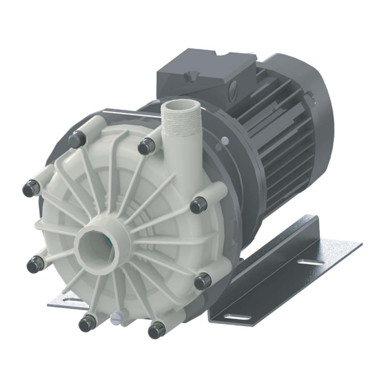
Magnetically driven spiral
cased centrifugal pump
Original operating manual
Version
BA-2018.08.21 EN
Print-No.
300 092
TR MA DE Rev004
Series SHM
STÜBBE GmbH & Co. KG
Hollwieser Straße 5
32602 Vlotho
Germany
Phone: +49 (0) 5733-799-0
Fax: +49 (0) 5733-799-5000
E-mail:
contact@stuebbe.com
Internet:
www.stuebbe.com
Subject to technical modifications.
Read carefully before use.
Save for future use.
Advertisement
Table of Contents

Subscribe to Our Youtube Channel
Related Manuals for Stübbe SHM Series


Summary of Contents for Stübbe SHM Series
- Page 1 Magnetically driven spiral cased centrifugal pump Original operating manual Series SHM Version BA-2018.08.21 EN STÜBBE GmbH & Co. KG Print-No. 300 092 Hollwieser Straße 5 32602 Vlotho TR MA DE Rev004 Germany Phone: +49 (0) 5733-799-0 Fax: +49 (0) 5733-799-5000 E-mail: contact@stuebbe.com Internet:...
-
Page 2: Table Of Contents
Table of contents Table of contents ....... 5.4.3 Installing the pressure pipe . - Page 3 Table of contents List of figures List of tables Fig. 1 Name plate (example) ..... . . Tab. 1 Other application documents, purpose and where found .
-
Page 4: About This Document
About this document About this document Other applicable documents This manual Document/purpose/ Where found • is part of the equipment ATEX additional manual (300 365) • applies to all series referred to • Additional instructions for use in • describes safe and proper operation during all operating explosive atmospheres phases •... -
Page 5: Warnings And Symbols
About this document Warnings and symbols Symbol Meaning • Immediate acute risk • Death, serious bodily harm • Potentially acute risk • Death, serious bodily harm • Potentially hazardous situation • Minor injury • Potentially hazardous situation • Material damage Safety warning sign Take note of all information highlighted by the safety warning... -
Page 6: General Safety Instructions
General safety instructions General safety instructions Prevention of obvious misuse (examples) • Observe pump limits of use regarding temperature, pres- sure, flow and speed (→ data sheet). The manufacturer accepts no liability for damages caused • The power consumption of the pump increases as the spe- by disregarding any of the documentation. -
Page 7: Obligations Of The Operating Company
General safety instructions 2.2.2 Obligations of the operating company 2.2.3 Obligations of personnel • All directions given on the pump must be followed (and kept Safety-conscious working legible), e.g. the arrow indicating the sense of rotation and • Operate the pump only if it is in perfect technical condition the markings for fluid connections. -
Page 8: Specific Hazards
General safety instructions Specific hazards 2.3.1 Hazardous pumped liquids • When handling hazardous fluids, observe the safety regu- lations for the handling of hazardous substances. • Use personal protective equipment when carrying out any work on the pump. • Collect leaking pumped liquid and residues in a safe man- ner and damage them in accordance with environmental regulations. -
Page 9: Layout And Function
Layout and Function Layout and Function Marking 3.1.1 Name plate Hollwieser Str. 5 D-32602 Vlotho Typ: Ser. NO.: ID. NO.: Mat.: M. Seal: Imp. Ø: /h H: Fig. 1 Name plate (example) Pump type Serial number Ident. number Housing / sealing material Shaft seal information Impeller diameter [mm] Differential head... -
Page 10: Description
Layout and Function Description Non self-priming, horizontal centrifugal pump. Magnetically coupled and hermetically sealed. BA-2018.08.21 EN 300 092... -
Page 11: Assembly
Layout and Function Assembly Fig. 3 Assembly Suction flange Terminal box Volute casing Pressure flange Motor Magnetic coupling Base frame Shaft seals Only one of the following shaft seals is used. 3.4.1 Magnetic coupling Magnetic coupling is hermetically sealed, no leakages. 300 092 BA-2018.08.21 EN... -
Page 12: Transport, Storage And Disposal
Transport, Storage and Disposal Transport, Storage and Disposal Transport The user/owner is responsible for the transport of the pump. Weight specifications (→ documents for the particular order) 4.1.1 Unpacking and inspection on delivery 1. Unpack the pump/pump assembly upon delivery and inspect it for transport damage. -
Page 13: Lifting
Transport, Storage and Disposal Storage 4.1.2 Lifting DANGER NOTE Death or limbs crushed as a result transported items Material damage due to inappropriate storage! falling over! Store the pump properly. Use lifting gear appropriate for the total weight to be trans- ported. -
Page 14: Installation And Connection
Installation and connection Installation and connection 5.1.3 Prepare foundation and surface Aids, tools, materials: – Steel shims For pumps in potentially explosive atmospheres (→ ATEX – Spirit level additional manual). Installation options: – With concrete foundation – With steel foundation frames NOTE –... -
Page 15: Installing With Foundation
Installation and connection Installing with foundation Planning pipelines Water hammer may damage the pump or the system. Plan NOTE the pipes and fittings as far as possible to prevent water hammer occurring. Material damage due to distortion of base plate. Position the base plate as follows on the foundation and 5.3.1 Specifying supports and flange connections... -
Page 16: Specifying Pipe Lengths
Installation and connection 5.3.4 Specifying pipe lengths 5.3.7 Providing safety and control devices (recommended) Avoid contamination 1. Install filters in the suction pipe. 2. Install a differential pressure gauge with contact manome- ter to monitor contamination. Avoid reverse running 1. Install a non-return valve between the discharge flange and stop valve, to ensure that the medium does not flow back after the pump is switched off. -
Page 17: Connecting The Pipes
Installation and connection Connecting the pipes Electrical connection NOTE DANGER Material damage due to excessive forces and torques on Risk of electrocution! the pump. All electrical work must be carried out only by qualified elec- Ensure pipe connection without stress. tricians. -
Page 18: Operation
Operation Operation Commissioning 6.2.1 Switching on For pumps in potentially explosive atmospheres (→ ATEX Pump set up and connected properly additional manual). Motor set up and connected properly Align motor precisely to the pump All connections stress-free and sealed Preparing for commissioning All safety equipment installed and tested for functionality 6.1.1 Check downtimes... -
Page 19: Switching Off
Operation 6. Make sure temperature change is smaller than 5 K/min for Take the following measures whenever the pump is shut pumps with hot fluids. down: 7. After the initial stress due to the pressure and operating Pump is Action temperature, check that the pump is not leaking. -
Page 20: Restoring The Pump To Service
Operation Restoring the pump to service 1. Complete steps commissioning (→ 6.2 Commissioning, Page 18). 2. If the pump is shut down for over 1 year, replace elastomer seals (O-rings, shaft sealing rings). Operating the stand-by pump Stand-by pump filled and bled Operate the stand-by pump at least once a week. -
Page 21: Maintenance
Maintenance Maintenance Servicing Operating life of antifriction bearings when operated within the permissible range: >2 years. For pumps in potentially explosive atmospheres (→ ATEX additional manual). Intermittent operation, high temperatures, low viscosities and aggressive ambient and process conditions reduce the Trained service technicians are available for fitting and service life of antifriction bearings. -
Page 22: Maintenance In Accordance With Maintenance Schedule
Maintenance Dismounting WARNING Risk of injury and poisoning due to hazardous or hot fluid! DANGER Use personal protective equipment when carrying out any work on the pump. Danger to life and material damage due to magnetic field. Allow the pump to cool completely before commencing any Make sure that personnel with pacemakers do not com- work. -
Page 23: Preparations For Dismounting
Maintenance WARNING 7.3.1 Preparations for dismounting Pump is depressurized Risk of injury during disassembly! Pump completely empty, flushed and decontaminated Secure the pressure-side gate valve against accidental Electrical connections disconnected and motor secured opening. against switch-on Depressurize the blocking pressure system, if available. Pump cooled down Wear protective gloves, components can become very Coupling guard removed... -
Page 24: Dismantling Shm 40-40 To 65-50
Maintenance Replacement parts and return 7.3.3 Dismantling SHM 40-40 to 65-50 1. Attach lifting gear to the motor and gently lift. 1. Have the following information ready to hand when order- 2. Undo the screws (901.2). ing spare parts (→ type plate). 3. -
Page 25: Installing
Maintenance Installing NOTE Material damage due to unsuitable components! Install components concentrically and without tilting in Always replace lost or damaged screws with screws of the accordance with the markings applied. same strength where required (→ 9.2.8 Minimum flow rate, Page 33). -
Page 26: Troubleshooting
Troubleshooting Troubleshooting For pumps in potentially explosive atmospheres (→ ATEX additional manual). DANGER Danger to life and material damage due to magnetic field. Make sure that personnel with pacemakers do not com- plete work on the pump. Secure the work place and if necessary cordon off: –... - Page 27 Troubleshooting Fault number Remedy Cause – – – – – Suction head too large: NPSH is larger Increase pump inlet pressure. pump than NPSH Consult the manufacturer. system — X — X — X — — Back pressure of the system is too high, Consult the manufacturer.
- Page 28 Troubleshooting Fault number Remedy Cause – – – – Motor speed too high Compare the required motor speed with the specifications on the pump type plate. Replace the motor if necessary. Reduce the motor speed if speed control is available. –...
-
Page 29: Appendix
Appendix Appendix Replacement parts 9.1.1 Part numbers and designations Part no. Designation 102.1 Volute casing 210.1 Shaft 230.1 Impeller 314.3 Axial bearing 314.4 Axial bearing 314.5 Axial bearing 341.01 Pump mounting bracket 412.1 Sealing ring 412.2 Sealing ring 412.5 Sealing ring 505.1 Reinforcement ring 545.1... -
Page 30: Drawing Shm 20-15
Appendix 9.1.2 Drawing SHM 20-15 904.1 341.1 801.1 817.1 554.2 901.2 314.5 545.1 230.1 412.5 210.1 545.1 314.3 102.1 934.1 901.1 554.1 580.1 Fig. 7 Replacement parts SHM 20-15 BA-2018.08.21 EN 300 092... -
Page 31: Drawing Shm 40-40 To 65-50
Appendix 9.1.3 Drawing SHM 40-40 to 65-50 341.1 904.1 855.1 801.1 580.2 901.2 554.2 891.1 554.3 505.1 934.3 901.3 580.3 723.3 723.1 412.1 314.4 412.2 314.5 817.1 723.2 412.5 210.1 230.1 545.1 314.3 102.1 934.1 723.4 554.1 901.1 580.1 Fig. 8 Replacement parts SHM 40-40 to 65-50 300 092 BA-2018.08.21 EN... -
Page 32: Technical Specifications
Appendix Technical specifications 9.2.3 Flange tightening torques Further technical data (→ data sheet). Tightening torque MD [Nm] for the versions 9.2.1 Ambient conditions Flat sealing Profile O-ring [mm] [mm] ring sealing max. Operation under any other ambient conditions should be up to max ring 16 bar... -
Page 33: Sound Pressure Level
Appendix 9.2.6 Sound pressure level Maximum noise level LpA for 2-pole 50Hz/60Hz motors, in dB Size SHM20-15, SHM40-40S und SHM40-40L Motor power 0.18 kw 0.25 kw 0.37 kw 0.55 kw 0.75 kw 1.10 kw 1.5 kw rating Frequency SHM20-15 SHM40-40S SHM40-40L Tab. -
Page 34: Maintenance Schedule
Appendix Maintenance schedule Designation Interval Maintenance Self-priming container daily Check filling level. Conveyed fluid daily Check temperature Check discharge pressure. Operating temperatures Weekly Check motor temperature. Undoable screwed connections quarterly Check for correct and tight fitting. Impeller Check components for wear and damage Plain bearing required Clean or replace the impeller. -
Page 35: Declaration Of Conformity In Accordance With Ec Machinery Directive
Appendix Declaration of conformity in accordance with EC machinery directive EU Declaration of Conformity Stübbe GmbH & Co. KG, Hollwieser Straße 5, 32602 Vlotho, Germany, declares on its own authority that the following products Description Centrifugal pumps with mechanical seal NM, NMB, NX, SHB Magnetically-coupled pumps Eccentric pumps...
Need help?
Do you have a question about the SHM Series and is the answer not in the manual?
Questions and answers