
Subscribe to Our Youtube Channel
Related Manuals for PanelClaw Polar Bear East/West 10 Degree


Summary of Contents for PanelClaw Polar Bear East/West 10 Degree
- Page 1 Polar Bear® East/West for 10 Degree Installation Manual 9910022 Rev A QIMS.E339731 QIMS2.E339731 Polar Bear FR Gen II Module Mounting Attachment panelclaw.com...
-
Page 2: Revision History
Revision History ECO # Date Description of Changes Approved By C00270 21-MAY-13 INITIAL RELEASE Polar Bear East/West 10 Degree Installation Manual 9910022 Rev A... -
Page 3: Table Of Contents
Revision History ............................2 Table of Contents ............................3 Introduction ..............................4 Document Objective ............................. 4 Polar Bear East/West 10 Degree Components ..................... 5 Required Tools .............................. 6 Installation ..............................6 Step 1: Mark Array Perimeter and Assemble Supports ................6 Step 2. -
Page 4: Introduction
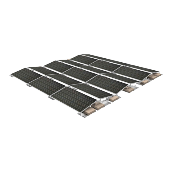
Introduction Polar Bear East/West 10 Degree is designed to maximize array construction speed and minimize construction risk. Polar Bear’s patent pending, innovative, streamlined construction features: Just two major components plus only one nut and bolt size Several labor saving factory-installed features ... -
Page 5: Polar Bear East/West 10 Degree Components
Polar Bear East/West 10 Degree Components This is a parts list for a ballasted Polar Bear® East/West 10 Degree installation not requiring mechanical attachment. Please refer to the PanelClaw Roof Connector Installation Manual, available at www.panelclaw.com, for instructions on mechanical attachment of the system. -
Page 6: Required Tools
Tools Required 9/16” Wrench or socket Installation Polar Bear East/West 10 Degree can be installed in 5 easy steps. Step 1: Mark Array Perimeter and Assemble Supports No tools are required for Support assembly. Mark the array perimeter using a chalk line or similar method. See site’s Ballast Layout Drawing provided by PanelClaw for array dimensions. -
Page 7: Step 2. Lay Out Supports And Add Ballast
Spacer Sticks in position. Note: The Spacer Stick lengths can also be established by using the procedure found in Appendix C. Polar Bear East/West 10 Degree Installation Manual 9910022 Rev A... - Page 8 East (Figure 4, Figure 5). PanelClaw recommends starting the array in a corner with low complexity and moving outwards in a direction that best suits the individual array you are building (e.g. rows and columns with the least number of interruptions/breaks).
- Page 9 Position “D” Claws) or “B” (Long Claw) (Note Support Orientation) (Note Support Orientation) Figure 4 Completed Support Assembly West Side Note Orientation West Note Positioning Figure 5 Support Positioning Middle Polar Bear East/West 10 Degree Installation Manual 9910022 Rev A...
- Page 10 Solid Cap Concrete blocks as ballast (not provided). Each block has nominal dimensions of 4” x 8” x 16” and nominal weight of 26 lb. (11.8 kg). Blocks of various weights may be used in advance consultation with PanelClaw’s engineering department. Various possible Ballast Block configurations are shown below (Figure Note: Blocks should not be stacked on top of each other.
-
Page 11: Step 3. Attach Claws To Module
Figure 7 Ballast Layout Step 3: Attach Claws to Module PanelClaw offers three Claw options to accommodate different frame types, Standard (Claw I), Multi- piece (Claw III), and Long (Longitudinal). The following directions are for the Standard Claw (Claw I), for Multi-piece and Long Claw mounting instructions please see Appendix A. -
Page 12: Step 4. Mount Modules To Supports
(to the North or South). A 3/8-16 serrated flange nut should then be finger tightened Figure 9 on the Eastern (or Western)-most Support only to initially secure the module ( Polar Bear East/West 10 Degree Installation Manual 9910022 Rev A... -
Page 13: East/West Support
Support to be installed (to the East) (Figure 10 Figure 11). Claw PV Module East/West Support High End Exterior Low Support Figure 10 Tilt Module to Attach East/West Support Polar Bear East/West 10 Degree Installation Manual 9910022 Rev A... -
Page 14: Step 5. Electrical Grounding
The Polar Bear mounting system is UL and ETL listed to UL 2703 (Rack Mounting Systems and Clamping Devices for Flat-plate Photovoltaic Modules and Panels). Polar Bear mounting systems enable installers using modules included in PanelClaw’s UL 2703 listings to quickly and easily establish UL/ETL-certified electric bonds between all connected array components, including modules and mounting system components, without the use of additional grounding devices, e.g. - Page 15 Additional information regarding UL 2703 and the specific modules included in PanelClaw’s UL and ETL listings can be found in the PanelClaw UL & ETL Overview (UL 2703) document (available at www.panelclaw.com). For modules that are listed, please follow the instructions. For unlisted and unapproved modules follow the grounding instructions in Appendix E.
-
Page 16: Technical Support
DC grounded location outside of the array. 5. Verify every independent array section includes at least one grounding device/lug. Technical Support To contact PanelClaw Customer Technical Support, call +1 978.688.4900 or email technicalsupport@panelclaw.com. Polar Bear East/West 10 Degree Installation Manual... -
Page 17: Appendix A: Alternate Claw Attachment To Module
Figure 13 Long Claw Detail Place a PV module face down on a protected work surface ( Figure 14). Long Side Flange Short Side Flange Figure 14 Place Module Face Down Polar Bear East/West 10 Degree Installation Manual 9910022 Rev A... - Page 18 5. Secure the Long Claw with the hardware provided, ensuring that the bolt is inserted from the underside of the flange and facing up (Figure 17 and Figure 18). Torque the hardware to the module manufacturer’s specifications. Polar Bear East/West 10 Degree Installation Manual 9910022 Rev A...
- Page 19 Figure 17 Install Hardware Bolt Long Claw Long Side Flange Top Side of Module Figure 18 Cross Sectional Detail of Installed Long Clamp Polar Bear East/West 10 Degree Installation Manual 9910022 Rev A...
- Page 20 Ensure that the hex head cap screws are inserted into the Support mounting holes so the threaded end of each hex head cap screw faces the next Support to be installed (Figure 20). Polar Bear East/West 10 Degree Installation Manual 9910022 Rev A...
- Page 21 EAST 3/8-16 Serrated Flange Nut 3/8-16 x 1.25 Hex Head Cap Screw Mounting Hole Marked “2” Figure 20 Module Attachment to Support Polar Bear East/West 10 Degree Installation Manual 9910022 Rev A...
- Page 22 Claw is seated over the module frame, with the tab flush against the short side of the module as shown in the image below. Figure 21 Multi-piece Claw Detail Contact PanelClaw Customer Technical Support for additional information about alternative Claws. Polar Bear East/West 10 Degree Installation Manual 9910022 Rev A...
-
Page 23: Appendix B: Safety
The subsections below outline some of the obvious / major hazards that could exist during the installation of PanelClaw products, and are divided to bring a level of clarity to such hazards. Some sections do not apply to all PanelClaw product lines and such exclusions are noted within each section. - Page 24 Material Handling: All PanelClaw parts and components are made of aluminum and steel alloys and utilize stainless steel assembly hardware. These materials are considered non-toxic and require no special handling procedures. Metal components may have sharp edges, so be sure to handle with care and utilize proper personal protection equipment, especially gloves, during handling.
-
Page 25: Appendix C: Spacer Sticks
Appendix C: Spacer Sticks To assist in proper row and module spacing, PanelClaw makes Spacer Sticks available. These tools are easily employed to ensure module supports are properly spaced in the array. To assemble the Spacer Sticks please follow the directions below. -
Page 26: Appendix D: Electric Grounding (Ul 2703 Not Applicable)
Tighten each Tyco solid wire grounding assembly to torque of 45 in-lb (5.08 N-m), as in Figure 23 below. Please note that the pre-attached Tyco wire grounding assembly has been tightened to 25 in-lb (2.82 N- Copper Wire Tyco Lug Figure 23 Electrical Grounding Polar Bear East/West 10 Degree Installation Manual 9910022 Rev A...
Need help?
Do you have a question about the Polar Bear East/West 10 Degree and is the answer not in the manual?
Questions and answers