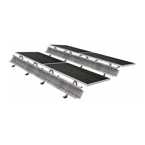
Summary of Contents for PanelClaw Polar Bear III 10 Degree
- Page 1 Polar Bear® III 10 Degree Installation Manual Document Number 9910030 Rev B January 2015 Classified for electrical bonding and grounding under UL 2703 panelclaw.com...
-
Page 2: Revision History
Revision History ECO # Date Description of Changes Approved By C00385 29-AUG-14 Release of Polar Bear III 10 degree C00398 16-JAN-15 UL 2703 Fire Update & 2 flat Ballast Tray Polar Bear III 10 Degree Installation Manual 9910030 Rev B... -
Page 3: Table Of Contents
Step 5: Electrical Grounding ........................12 Appendix A: Safety ............................14 Appendix B: UL 2703 Grounding ......................... 16 Appendix C: Electrical Grounding (UL 2703 not applicable) ............... 17 Appendix D: Side Shield (Optional) ......................18 Polar Bear III 10 Degree Installation Manual 9910030 Rev B... -
Page 4: Introduction
/ major hazards that could exist during the installation of PanelClaw products, and are divided to bring a level of clarity to such hazards. Some sections do not apply to all PanelClaw product lines and such exclusions are noted within each section. -
Page 5: Parts And Hardware
Ballast Block Mechanical Attachments (Customer supplied) OMG Roofing Products: PowerGrip OMG Roofing Products: PowerGrip Plus EcoFasten® Solar Anchor Products: U-Anchor 2000 Anchor Products: U-Anchor 2400 Anchor Products: U-Anchor 2600 Polar Bear III 10 Degree Installation Manual 9910030 Rev B... -
Page 6: Required Tools
5. Press Claw firmly against module frame and tighten bolt to 8 ft-lbs of torque (Figure 6. Repeat Steps 2 through 5 for the other three Claws. Figure 1 Claw Placement on Module Polar Bear III 10 Degree Installation Manual 9910030 Rev B... -
Page 7: Step 2: Set Up Spacer Stick
Claw to a hole at one end of the Spacer Stick. Set the longer Claw to the dimension specified. Repeat for the smaller dimension. If the Q or L spacing has interference on the Spacer Stick relocate the first Claw. Figure 2 Spacer Stick Polar Bear III 10 Degree Installation Manual 9910030 Rev B... -
Page 8: Step 3: Build Southern Row Of Modules
Ensure that a slot in the short tray aligns with the south support riv-nut on the last support in the row. Polar Bear III 10 Degree Installation Manual 9910030 Rev B... - Page 9 15. Repeat Steps 9 through 14 for southern row. Be sure to use inter-column spacer, a standard support turned upside down between modules, to ensure that a 1”spacing is maintained. Polar Bear III 10 Degree Installation Manual 9910030 Rev B...
- Page 10 6). NOTE: Do not fasten Long Ballast Trays together where they overlap. See note 16 No hardware required where Long Ballast Trays overlap Figure 6 Attach Long Ballast Trays to Supports Polar Bear III 10 Degree Installation Manual 9910030 Rev B...
-
Page 11: Step 4: Install Array Row-By-Row
Double Capacity Support may be required based on the project’s design criteria. If the project utilizes North Double Capacity Supports Ballast Trays are installed in both the inclined position and flat position of the Supports in a similar fashion to the south array construction. Polar Bear III 10 Degree Installation Manual 9910030 Rev B... -
Page 12: Step 5: Electrical Grounding
Once the groupings of strings at equipotential have been determined, a Tyco solid wire grounding assembly must be attached to one Ballast Tray within each group of strings. PanelClaw’s Polar Bear Ballast Trays have a hole to which this grounding device/lug can be attached (see Figure 8). - Page 13 Figure 8 Ground Holes in Ballast Trays Polar Bear III 10 Degree Installation Manual 9910030 Rev B...
-
Page 14: Appendix A: Safety
The subsections below outline some of the obvious / major hazards that could exist during the installation of PanelClaw products, and are divided to bring a level of clarity to such hazards. Some sections do not apply to all PanelClaw product lines and such exclusions are noted within each section. - Page 15 All required tools to perform the installation of PanelClaw racking are outlined in the installation procedure. All tools should be inspected daily and before use by the operator. If any tool appears to be defective, stop the use of such equipment immediately, and ensure it is replaced before work continues.
-
Page 16: Appendix B: Ul 2703 Grounding
Appendix B: UL 2703 Grounding PanelClaw components within the array are required to be electrically bonded to other DC grounding paths via the use of either #8 or #6 AWG Cu bonding jumpers and a UL 467 listed Tyco solid wire grounding assembly, part number 2106831, manufactured by Tyco Electronics Corporation. -
Page 17: Appendix C: Electrical Grounding (Ul 2703 Not Applicable)
Tighten each Tyco solid wire grounding assembly to torque of 45 in-lb (5.08 N-m), as shown below. Please note that the Tyco wire grounding assembly must be tightened to 25 in-lb (2.82 N-m). Bonding path from Lug to System (TYP) Ground Lug Tyco #2106831 Polar Bear III 10 Degree Installation Manual 9910030 Rev B... -
Page 18: Appendix D: Side Shield (Optional)
NOTE: To maximize packaging density the Side Shields may arrive with the integrated rubber pads unassembled. To assemble, use the push fastener to secure the rubber pad to the bottom of the Side Shield. Polar Bear III 10 Degree Installation Manual 9910030 Rev B... - Page 19 Ballast Trays is not allowed. A Fire Class A rating is achieved with Type II modules as long as the north double-capacity flat Ballast Trays are not used. Polar Bear III 10 Degree Installation Manual 9910030 Rev B...


Need help?
Do you have a question about the Polar Bear III 10 Degree and is the answer not in the manual?
Questions and answers