
Related Manuals for Thermo King E-Series


Summary of Contents for Thermo King E-Series
- Page 1 Operator’s Manual E-Series Units with Direct Smart Reefer E-200 Revision B T T K K 6 6 1 1 6 6 5 5 2 2 - - 1 1 8 8 - - O O P P - - E E N N...
- Page 2 If more information is required, consult your Thermo King Service Directory for the location and telephone number of the local dealer. T T h h e e r r m m o o K K i i n n g g ’ ’ s s w w a a r r r r a a n n t t y y s s h h a a l l l l n n o o t t a a p p p p l l y y t t o o a a n n y y e e q q u u i i p p m m e e n n t t w w h h i i c c h h h h a a s s b b e e e e n n “...
- Page 3 At this point you can give details of the service required and the repair will be organized. No payment at point of repair for customers with a ThermoKare service contract or with a guaranty of payment from their Thermo King home-dealer TK 61652-18-OP-EN...
- Page 4 General Inquires and Unit Maintenance For general inquiries please contact your local Thermo King dealer. Go to www.europe.thermoking.com and select dealer locator for your local Thermo King dealer. Or refer to the Thermo King Service Directory for contact information. TK 61652-18-OP-EN...
- Page 5 I I n n t t r r o o d d u u c c t t i i o o n n Customer Satisfaction Survey Let your voice be heard! Your feedback will help improve our manuals. The survey is accessible through any internet-connected device with a web browser.
-
Page 6: Table Of Contents
Table of Contents S S a a f f e e t t y y P P r r e e c c a a u u t t i i o o n n s s ..................9 9 Danger, Warning, Caution, and Notice . - Page 7 T T a a b b l l e e o o f f C C o o n n t t e e n n t t s s Electrical System ......... . 30 Fuses .
- Page 8 T T a a b b l l e e o o f f C C o o n n t t e e n n t t s s L L o o a a d d i i n n g g a a n n d d I I n n s s p p e e c c t t i i o o n n P P r r o o c c e e d d u u r r e e s s ..........5 5 1 1 Post-Start Inspection .
-
Page 9: Danger, Warning, Caution, And Notice
Safety Precautions Danger, Warning, Caution, and Notice Thermo King® recommends that all service be performed by a Thermo King dealer and to be aware of several general safety practices. Safety advisories appear throughout this manual as required (refer to examples below). Your personal safety and the proper operation of this unit depend upon the strict observance of these precautions. -
Page 10: General Safety Practices
Do not replace the battery with any type other than the one approved by Thermo King for this unit. W W A A R R N N I I N N G G R R i i s s k k o o f f I I n n j j u u r r y y ! ! Do not apply heat to a closed cooling system. - Page 11 S S h h a a r r p p E E d d g g e e s s ! ! Exposed coil fins can cause lacerations. Service work on the evaporator or condenser coils is best left to a certified Thermo King technician. TK 61652-18-OP-EN...
-
Page 12: Automatic Start/Stop Operation
H H a a z z a a r r d d o o f f E E x x p p l l o o s s i i o o n n ! ! An improperly installed battery could result in a fire, explosion, or injury. A Thermo King approved battery must be installed and properly secured to the battery tray. - Page 13 E E q q u u i i p p m m e e n n t t D D a a m m a a g g e e ! ! Do not connect other manufacturer’s equipment or accessories to the unit or to the TK Batteries unless approved by Thermo King. Failure to do so can result in severe damage to equipment and void the warranty.
-
Page 14: Refrigerant
S S a a f f e e t t y y P P r r e e c c a a u u t t i i o o n n s s Refrigerant Although fluorocarbon refrigerants are classified as safe, use caution when working with refrigerants or in areas where they are being used. -
Page 15: Refrigerant Oil
S S a a f f e e t t y y P P r r e e c c a a u u t t i i o o n n s s Refrigerant Oil Observe the following precautions when working with or around refrigerant oil: W W A A R R N N I I N N G G P P e e r r s s o o n n a a l l P P r r o o t t e e c c t t i i v v e e E E q q u u i i p p m m e e n n t t ( ( P P P P E E ) ) R R e e q q u u i i r r e e d d ! ! - Page 16 S S a a f f e e t t y y P P r r e e c c a a u u t t i i o o n n s s • E E y y e e s s : : Immediately flush with large amounts of water for at least 15 minutes.
-
Page 17: Safety Decals
S S a a f f e e t t y y P P r r e e c c a a u u t t i i o o n n s s Move victim to fresh air and use Cardio Pulmonary Resuscitation (CPR) or mouth-to-mouth resuscitation to restore breathing, if necessary. -
Page 18: Operation
S S a a f f e e t t y y P P r r e e c c a a u u t t i i o o n n s s Operation The Operation decal is located in an appropriate position near your in-cab controller (HMI). -
Page 19: Condenser And Evaporator Fans
On/Off switch Off before doing inspections or working on any part of the unit. Please note that only Qualified and Certified personnel should attempt to service your Thermo King unit. Decals located on the cover of the electrical box, condenser section. -
Page 20: Refrigerant
S S a a f f e e t t y y P P r r e e c c a a u u t t i i o o n n s s Figure 4. Unit Auto-start Warning Refrigerant Refrigerant Decal is located adjacent to the service ports for charging or recovering the gas, as per the F-Gas regulation. -
Page 21: Type Certification
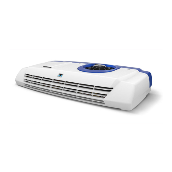
S S a a f f e e t t y y P P r r e e c c a a u u t t i i o o n n s s Type Certification UNECE R10 decal sample. TK 61652-18-OP-EN... - Page 22 Unit Description Thermo King Vehicle Powered Truck Units are two-piece units comprised of a condenser and evaporator designed for fresh, frozen, and deep frozen applications on small trucks and vans. Operated by a variable speed hermetic compressor. During road operation, energy is provided by the vehicle (if available) or by TK batteries (See “Options,”...
-
Page 23: U U N N I I T T D D E E S S C C R R I I P P T T I I O O N
U U n n i i t t D D e e s s c c r r i i p p t t i i o o n n Standard Unit Features • C C o o n n d d e e n n s s e e r r - Lightweight design of aluminium construction, easy to service with automotive grade polypropylene cover. -
Page 24: System Components
The system consists of the following main components: Compressor(s) With E-Series units, mobile operation and electric standby modes operate with a compressor driven by an DC/AC inverter. Power is taken from vehicle battery or auxiliary batteries in mobile operation or from shore power in electric standby. -
Page 25: Electronic Control System
Electronic Control System The Electronic Control System is composed of an Electronic Control Module (DSR-IV controller - located inside the condenser unit) and the HMI. This HMI allows the truck driver to operate the Thermo King refrigeration unit. Figure 6. Description The Electronic Control System has the following characteristics: •... - Page 26 U U n n i i t t D D e e s s c c r r i i p p t t i i o o n n • Electric Standby Compressor Hourmeter • Low Battery Voltage Alarm •...
-
Page 27: Unit Controls
U U n n i i t t D D e e s s c c r r i i p p t t i i o o n n R R e e t t u u r r n n A A i i r r T T e e m m p p e e r r a a t t u u r r e e S S e e n n s s o o r r : : On-screen reading of the temperature in the load compartment. -
Page 28: Standby Operation
U U n n i i t t D D e e s s c c r r i i p p t t i i o o n n 7. Buzzer It is energised when the vehicle battery and the electric power supply are connected simultaneously. - Page 29 U U n n i i t t D D e e s s c c r r i i p p t t i i o o n n Figure 8. Standby Power Receptacle TK 61652-18-OP-EN...
-
Page 30: Electrical System
START/STOP activation (Eg. Traffic jam, urban distribution with high density of traffic lights,…). These require external vehicle supports for control of START/STOP and idle speed increase. Consult with your Thermo King Dealer Representative for further information. Fuses The electrical components are protected by various fuses. - Page 31 U U n n i i t t D D e e s s c c r r i i p p t t i i o o n n I I g g n n i i t t i i o o n n P P o o w w e e r r F F u u s s e e - The ignition power fuse is connected to the vehicle’s fused ignition system.
-
Page 32: General Operation
Operating Instructions General Operation In truck-driven units, temperature control is based on two values: The setting (Setpoint) of the electronic thermostat and the evaporator return temperature. The difference between these two temperatures will determine the mode of operation: cool, heat, or null. •... -
Page 33: Starting The Unit
Y Y e e a a r r o o f f m m a a n n u u f f a a c c t t u u r r e e : : Reference Serial Plate. Installation and commissioning are to be carried out by an authorised Thermo King Dealer in accordance with Thermo King procedures and drawings. Exceptions to this with the written authorisation of the manufacturer only. -
Page 34: Standard Display
O O p p e e r r a a t t i i n n g g I I n n s s t t r r u u c c t t i i o o n n s s N N o o t t e e s s : : 1. -
Page 35: Entering Setpoint Temperature
Setpoint Temperature. Multi-Temperature Units N N o o t t e e : : Since software MSK 544.03, Thermo King has introduced a Zone Priority function which allows Spectrum units to provide cooling or heating priority for a specific zone to satisfy setpoint as soon as possible. - Page 36 O O p p e e r r a a t t i i n n g g I I n n s s t t r r u u c c t t i i o o n n s s 1.
-
Page 37: Compartment Selection
O O p p e e r r a a t t i i n n g g I I n n s s t t r r u u c c t t i i o o n n s s Compartment Selection 1. - Page 38 O O p p e e r r a a t t i i n n g g I I n n s s t t r r u u c c t t i i o o n n s s •...
-
Page 39: Initiating The Evaporator Manual Defrost Cycle
O O p p e e r r a a t t i i n n g g I I n n s s t t r r u u c c t t i i o o n n s s –... - Page 40 O O p p e e r r a a t t i i n n g g I I n n s s t t r r u u c c t t i i o o n n s s 3.
-
Page 41: Tk Batteries Hmi Menu
O O p p e e r r a a t t i i n n g g I I n n s s t t r r u u c c t t i i o o n n s s TK Batteries HMI Menu Figure 10. -
Page 42: Road Mode
O O p p e e r r a a t t i i n n g g I I n n s s t t r r u u c c t t i i o o n n s s •... -
Page 43: Tk Hold-Over Mode
O O p p e e r r a a t t i i n n g g I I n n s s t t r r u u c c t t i i o o n n s s TK Hold-Over Mode When the IGNITION is OFF and in is NOT connected to Shore Power, is possible to start the unit in HoldOver Mode, this means the power to run the... -
Page 44: Alarms
O O p p e e r r a a t t i i n n g g I I n n s s t t r r u u c c t t i i o o n n s s Alarms When the unit is not operating properly, the microprocessor records the alarm code, alerts the operator by displaying the Alarm symbol and,... -
Page 45: Buzzers
O O p p e e r r a a t t i i n n g g I I n n s s t t r r u u c c t t i i o o n n s s If it is a multi-temperature unit, the —... -
Page 46: Alarm Code Descriptions
King Dealer. High Pressure Sensor Failure - The high pressure sensor has become faulty or disconnected. Contact your Thermo King Dealer. dr1, dr2 Cargo Doors Are Open (Units with door switch option only) - Check if the Doors are open. if not, then the door switches are faulty, or improper door switch configuration. - Page 47 - An error occurred while loading parameters to the DSR-IV Controller. Internal, System reset needed, contact your Thermo King Dealer. eMMC write error - An error occurred while loading parameters to the DSR-IV Controller or performing the datalogging process.
- Page 48 Flash Loading Failed - An error occurred while loading firmware to the DSR-IV Controller. Internal, System reset needed, contact your Thermo King Dealer. Non-Compatible SW - Indicates that one of the Electronic components contains an incorrect or out-of-date Software version.
-
Page 49: Clearing Alarm Codes
Contact your Thermo King Dealer. Low Battery warning. - Please connect your unit to shore power to charge the TK Battery. If problem persists Contact your Thermo King Dealer. H60 to H63 Battery internal alarm (internal sensors) - Shutdown alarm Contact your Thermo King Dealer. -
Page 50: Viewing Information Screens
O O p p e e r r a a t t i i n n g g I I n n s s t t r r u u c c t t i i o o n n s s I I m m p p o o r r t t a a n n t t : : Continually clearing alarm codes without resolving the problem will result in damage to the unit and compressor. -
Page 51: Post-Start Inspection
DO NOT block the evaporator inlet or outlet. 4. Product should be pre-cooled before loading. Thermo King units are designed to maintain the load at the temperature at which it is loaded. Transport refrigeration units are not designed to reduce the load temperature. - Page 52 L L o o a a d d i i n n g g a a n n d d I I n n s s p p e e c c t t i i o o n n P P r r o o c c e e d d u u r r e e s s 2.
-
Page 53: Refrigeration System
Specifications Refrigeration System Contact your Thermo King dealer for refrigeration system service or maintenance. Compressor E-200 Compressor Type Electrical hermetic compressor, rotary type Oil Tyoe Electrical Control System 12 Vdc Fuses E-200 Fuse 1: Main Fuse 150 amps Fuse 3: Evaporator Fan... - Page 54 S S p p e e c c i i f f i i c c a a t t i i o o n n s s Fuse 8: 10 amps BMS Fuses Fuse 84: Condenser Fan Motor Voltage 13 Vdc Full Load Current 10 Amps...
- Page 55 S S p p e e c c i i f f i i c c a a t t i i o o n n s s Electrical output power: 1150 W continuous, 1400 W for 30 Smart Charger module Bidirectional battery Charger / Discharger Voltage 13 Vdc...
- Page 56 Warranty Please also refer to TK 61654-18-WA Thermo King EMEA Unit Limited Warranty for Vehicle Powered Truck Units. TK 61652-18-OP-EN...
-
Page 57: Weekly Pre-Trip Checks
Inspection and Service Intervals Weekly Pre-Trip Checks 1. Listen for unusual noises, vibrations, etc. 2. Visually inspect unit for fluid leaks (coolant, oil, refrigerant). 3. Visually inspect unit for damaged, loose or broken parts (including air ducts and bulkheads, if so equipped). 4. -
Page 58: Weekly Post-Trip Checks
4. Check for physical damage to the unit. Inspection and Service Schedules To ensure that your Thermo King unit operates reliably and economically over its full life, and to avoid limiting its warranty cover, the appropriate inspection and service schedule must be followed. Inspection and Service... -
Page 59: Service Record
Please work with your Dealer in order to create a maintenance schedule which fits your needs. Thermo King has extended the limited warranty on new units from 3,000 total hours to a maximum of 4,000 compressor run hours within the 2 year warranty period. - Page 60 Serial Number Locations 1. C C O O N N D D E E N N S S E E R R : : Nameplate located on the back of the condenser frame (Cover needs to be removed). 2. I I N N V V E E R R T T E E R R D D R R I I V V E E N N C C O O M M P P R R E E S S S S O O R R : : Nameplate located on compressor body.
- Page 61 S S e e r r i i a a l l N N u u m m b b e e r r L L o o c c a a t t i i o o n n s s Figure 12.
- Page 62 Recover Refrigerant At Thermo King®, we recognize the need to preserve the environment and limit the potential harm to the ozone layer that can result from allowing refrigerant to escape into the atmosphere. We strictly adhere to a policy that promotes the recovery and limits the loss of refrigerant into the atmosphere.
- Page 63 N N o o t t e e s s TK 61652-18-OP-EN...
- Page 64 1938. For more information, visit www. thermoking.com or www.tranetechnologies.com. Thermo King has a policy of continuous product and product data improvements and reserves the right to change design and specifications without notice. We are committed to using environmentally conscious print practices.
Need help?
Do you have a question about the E-Series and is the answer not in the manual?
Questions and answers