Table of Contents
Advertisement
Quick Links
Declaration of Conformity
Tri m ec Industries Pt y Ltd declares under sole responsibilit y that the products :
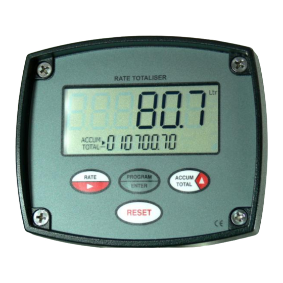
Flow rate totaliser
model : RT...
to w hi c h thi s declaration rel a tes are i n conformit y with the standards noted below :
EN 60529 : 1991 Degrees of protection (IP)
EN 61326 : 1998 Industrial electromagneti c i m munit y & emi s sions
2002/96/EC Waste electrical & electronic equi p ment (WEEE).
Issued at Taren Point 28
th
January 2010. Signed for and on behalf of Tri m ec Industries Pt y Ltd.
Wayne Fuller, Director
IMRT20D-2410
Utility Series
FLOW RATE TOTALISER
with backlighting & flow alarms
I N S T R U C T I O N
M A N U A L
Advertisement
Table of Contents

Related Manuals for Trimec RT Series


Summary of Contents for Trimec RT Series
- Page 1 Utility Series FLOW RATE TOTALISER with backlighting & flow alarms I N S T R U C T I O N M A N U A L Declaration of Conformity Tri m ec Industries Pt y Ltd declares under sole responsibilit y that the products : Flow rate totaliser model : RT…...
-
Page 2: Table Of Contents
TABLE OF CONTENTS INTRODUCTION Software issue Description of elements Specifications Overview LCD displays PROG OPERATION Accumulative total display Resettable total display Press & hold Program key to show Rate display instrument software version Keypad function matrix INSTALLATION Remote mounting - Surface mount footprint - wall / surface mount - panel mount - pipe mount... - Page 3 Introduction Introduction 1.1 Description of elements 1.2 Specifications Display : Large backlit 6 digit numeric display with LCD characters 17mm ( 0.67 ”) high, second line Processor Facia of 8 digits x 7mm high totalising plus 5 digits of rate indication. Programmable 0~ 3 decimal places for all displays.
-
Page 4: Keypad Function Matrix
6 Introduction Operation 1.3 Overview OPERATION The instrument will display Flow Rate, Resettable Total and an Accumulated Total in engineering units as programmed by the user. Simple flow chart programming prompts you through the programming set up greatly 2.1 Accumulati ve Total reducing the need to refer to the instruction manual. -
Page 5: Installation
Installation Installation 3.1 Remote Mounting (continued) INSTALLATION 3.1 Remote Mounting 42.6 mm * Pipe mount ( 1.67 ” ) Surface mount footprint * order Pipe mount kit P/No. APM use 4 x M3 screws comprising two brackets, supplied screws and worm drive clamps. RATE TO TALI SER ►... -
Page 6: Unpowered Sensors
Installation Installation 3.2 Flowmeter connections - powered sensors 3.2 Flowmeter connections - unpowered sensors 4. Hall effect ( 5~24Vdc open collector DIP swit ch functions : DIP SW2 (pull up) is on Switch 3 : ON engages 820Ω pull down resister Flow -0V (ground) High f low alarm... -
Page 7: External Powering
Installation Installation 13 3.3 Wiring connections (continued) 3.3 Wiring connections Pulse & Alarm Output (for thi s feature the instrument must be externall y powered as per page 12 ) The scaled pul s e output is in the form of an NPN (current sinking) st y le pulse capable of sw it c hing up to 100mA. External DC powering –... - Page 8 Programming Programming 4. PROGRAM PARAMETERS 4.8 Display priority The large digits at the top of the display can be programmed to show either flow rate or Note: The instrument defaults out of the program mode i f no programming entries are made after 4 minutes. resettable total.
-
Page 9: Scaled Pulse Output
Programming Programming Return to top RT20 of program ISSUE 1.0 RATE PROGR AM ACCU M HoLd Optional alarm outputs XXXXXX TO TAL ENTER 5 4 3 2 1 Lo - FLo 1) Low flow alarm (L o-Fl o) occurs whe n the f low f alls below the set point, High flow alarm (Hi.Flo) occurs when the f low goes abov e the set point. - Page 10 Panel mount template 19 Index ALPHABETICAL INDEX 89.6 mm ( 3.53” ) Accumulative total PIN number protection 14, 16 Programming 14, 15 Program detail record Battery 2, 5 Pulse output Backlighting the LCD display Rate response PANNEL CUT OUT : DC power 5, 12 71mm high x 83mm wide...
Need help?
Do you have a question about the RT Series and is the answer not in the manual?
Questions and answers