Table of Contents
Advertisement
Universal Mount Series
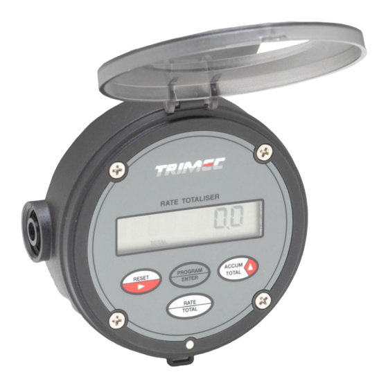
RT FLOW RATE TOTALISER
I N S T R U C T I O N
M A N U A L
Distributed by:
TRIMEC
INDUSTRIES Pty.Ltd.
1 / 19 Northumberland Road, Caringbah
( PO Box 2444 Taren Point )
Sydney 2229, NSW - AUSTRALIA
Tel : +61 2 9540 4433
Fax: +61 2 9525 9411
sales@trimecind.com.au
Email :
Website: www.trimecind.com
TRIMEC
Europe Ltd
Floor 3, 5A Boltro Road
Haywards Heath West Sussex,
UNITED KINGDOM RH16 1BP
Tel : +44 144-441-7880
Fax : +44 144-441-7668
Email : europe@trimecind.com
Website : www.trimecind.com
IMRTVDC-1105
Advertisement
Chapters
Table of Contents

Related Manuals for Trimec rt11


Summary of Contents for Trimec rt11
- Page 1 RT FLOW RATE TOTALISER I N S T R U C T I O N M A N U A L Distributed by: TRIMEC INDUSTRIES Pty.Ltd. 1 / 19 Northumberland Road, Caringbah ( PO Box 2444 Taren Point ) Sydney 2229, NSW - AUSTRALIA...
-
Page 2: Table Of Contents
- alarm outputs Accum. Total : The difference of A-B accum.tot. displayed as one total. - remote switches (refer page) PROGRAM PARAMETERS ( models RT11& RT12 ) Outputs Scaled Pulse : Scaled pulse value is relative to the totalised values. -
Page 3: Introduction
Rate totaliser, battery or DC powered with pulse outputs, 10 point NLC RT12 RT11 rate totaliser with 4~20mA & alarm outputs, dual flow inputs Electrical access 3 x M20 x 1.5mm f emale t hreaded conduit ent ry ports w ith knock-outs 3 x 1/2"... -
Page 4: Specifications
Introduction 1.2 Specifications Display : 8 digit alpha numeric LCD characters 9mm ( 0.35 ”) high with TERMINAL DESIGNATION second line sub script text, 8 digits totalising, 5 digits rate, 3 programmable decimal points with all displays. Terminal Terminal Signal Input : Universal pulse/frequency input compatible with Reed switch, High flow alarm 14 Flow... -
Page 5: Overview
Introduction Programming Program detail record 1.3 Overview Pencil your program details here The RT series instruments are specifically designed for computing, displaying and User selected PIN No. transmitting totals and flowrate from flowmeters with pulse or frequency outputs. Engineering units The instrument will display Flow Rate, Resettable Total and an Accumulated Total in K-factor (scale factor) engineering units as programmed by the user. -
Page 6: Operation
programming Operation OPERATION 6.2 Program levels 14~24 ( Model RT12 only ) 2.1 Accumulative Total Accumulative total can be reset at L2 in the program mode. The accumulative total can be ANALOG OUTPUT REQUIRED Y / N displayed momentarily or continuously through use of the front panel ACCUM TOTAL key. 4 ~ 20mA Y - N Momentary display : Accumulative total is displayed only whilst the key is held pressed. -
Page 7: Keypad Function Matrix
Operation Programming 15 2.6 Keypad function matrix 6.1 Program levels 8 ~ 13 (RT11 & 12) SET RATE DAMPENING FUNCTION IN OPERATING MODE FUNCTION IN PROGRAM MODE L9 SET LOW FREQUENCY CUT-OFF DAMP 00 ~ 99 RATE Displays Accumulative Total when pressed. -
Page 8: Pipe Mount
Programming Installation 3.1 Mounting (continued) PROGRAMMING FLOW CHART Program levels 1~7 (RT11 & 12) RT11 V3.0 HOLD 3 2 1 PROG TESTING DISPLAY 88888888 PROGRAM MODE ENTERED hold Program & Rate RATE keys for 5 secs to if PIN protected enter the program press Prog. -
Page 9: Flowmeter Connections - Unpowered Sensors
Installation Programming 3.2 Flowmeter connections ( unpowered sensors ) 4.10 Presetting battery power levels When the instrument is operated under battery power only a special “Power Mode” program option will appear at level 13 within the programming routine. A choice of three battery power Flow input A &... -
Page 10: Pulse Outputs
Installation PROGRAM PARAMETERS 3.2 Flowmeter connections ( powered sensors ) ( models RT11 & 12 ) 4.1 PIN No. Program Protection Any user defined PIN number other than 0000 will engage the program protection feature, 4. Hall effect ( 5~24Vdc open collector ) - Page 11 Installation Installation Pulse & Alarm Outputs 3.3 Wiring connections Current Sinking outputs ( NPN ) External DC powering Current sinking derives its name from the fact that it “sinks current from a load”. When activated the current flows from the load into the appropriate output (7,13 & 14). High flow alarm Flow Driving a logic input...
- Page 12 Page ALPHABETICAL INDEX Non linear correction Accumulative total Alarm deadband Alarm outputs Overview Software version Analog output Operation V 3.2 16.12.04 Output selector links Battery power levels PROG PIN number protection Presetting battery power levels DC power Programming 14 ~16 Press &...
- Page 13 POSITIVE DISPLACEMENT FLOWMETER Models : MP015 MP025 MP040 MP050 TRIMEC INDUSTRIES Pty.Ltd. Distributed by: 1 / 19 Northumberland Road Caringbah NSW 2229 INSTRUCTION MANUAL Sydney - AUSTRALIA Tel : +61 2 9540 4433 Fax: +61 2 9525 9411 Email : sales@trimecind.com.au Website: www.trimecind.com...
- Page 14 SPARE PARTS Item Description MP015 MP025 MP040 MP050 Piston Part Numbers PEEK 60ºC * SA1514 * SA2514 * SA4014 * SA5014 PEEK 120ºC * SA1515 * SA2515 * SA4015 * SA5015 CONTENTS Page PEEK 150ºC * SA1528 * SA2528 * SA4028 * SA5028 CFT 60ºC * SA1516...
- Page 15 MAINTENANCE OVERVIEW Dismantling The Multipulse flow meter is a precision machined positive displacement flow The Multipulse has been constructed in such a way that the flow meter meter capable of measuring a wide range of liquid flows and viscosities manifold need not be disturbed when servicing the flow meter in-situ. irrespective of their chemical or physical properties.
- Page 16 RT11 Flow Rat e Totaliser [not e 2] RT12 (RT11+ alarms & 4~ 20mA out put ) [not e 2] ( approximately 2ml ) so that there is about 2mm depth of coverage Ecobat ch dc bat ch cont roller...
- Page 17 Important: flow range is improved to within +/-0.5% when utilising the linearisation feature of the Hall effect output supply is to be optional Trimec RT flow rate totaliser. 5~24 Vdc MAX. voltage limited to 24Vdc maximum, should it be possible for the voltage to spike...
- Page 18 ELECTRICAL CONNECTIONS OPERATING PRINCIPLE Instrument cable Twisted pair low capacitance shielded instrument cable 7 x 0.3mm (0.5mm²) The Multipulse flow meter utilises the oscillating piston principle, where the should be used for electrical connection between the flow meter and the remote passage of liquid causes a piston to oscillate smoothly in a circular motion instrumentation.
- Page 19 The Multipulse positive displacement flow meter does not require any flow Meters fitted with the QP output option (quadrature pulse output) may be conditioning, therefore straight runs of pipe before and after the flow meter are interfaced with the Trimec Pulse Discriminator Module (PD1) to separate not necessary.
- Page 20 Spare parts diagram RIMEC New style O-ring configuration from year 2000 on...
- Page 21 RT SERIES FLOW RATE TOTALISER I N S T R U C T I O N M A N U A L Distributed by: TRIMEC INDUSTRIES Pty.Ltd. 2 / 1 Koonya Circuit (PO Box 2444) Taren Point NSW 2229 Sydney - AUSTRALIA...
-
Page 22: Flow Alarms
- external powering & remote reset - loop powering - scaled pulse output - alarm outputs - wiring requirements PROGRAM PARAMETERS ( models RT11& RT12 ) PIN number protection Resetting accumulative total Engineering units K-factor (scale factor) Rate conversion factor Rate dampening ( see response graph page 19 ) 12 &... - Page 23 Page Page Model number designation Rate dampening : Rate dampening value verses time to reach new reading ( for an instantaneous change in FUNCTION actual flow rate ) Rate totaliser SERIES 100 series ( field, panel or meter mount ) VERSIONS Scaled pulse output ( std.
- Page 24 Page Page 1.2 Specifications TERMINAL DESIGNATION Display : 8 digit alpha numeric LCD characters 9mm ( 0.35 ”) high with second line sub script text.. 8 digits totalising, 5 digits rate, 3 programmable decimal points with all displays. Terminal Signal Input : Universal pulse/frequency input compatible with Reed switch, DC power -0v Ground Common...
-
Page 25: Program Detail Record
Page Page Program detail record INTRODUCTION Pencil your program details here User selected PIN No. 1.3 Overview Engineering units The RT100 series instruments are specifically designed for computing, displaying and transmitting totals and flowrate from flowmeters with pulse or frequency outputs. K-factor (scale factor) Decimal for reset Total 000. - Page 26 Page Page PROGRAMMING FLOW CHART OPERATION 6.2 Program levels 13~23 2.1 Accumulative Total ( Model RT12 only ) Accumulative total can be reset at L2 in the program mode. The accumulative total can be ANALOG OUTPUT REQUIRED Y / N displayed momentarily or continuously through use of the front panel ACCUM TOTAL key.
-
Page 27: Installation
Page Page 15 INSTALLATION PROGRAMMING FLOW CHART 3.1 Mounting 6.1 Program levels 8 ~ 12 SET RATE DAMPENING TIP: holding the prog. key for 3 sec’s MP040 RATE TOTALISER PROG quick tracks to the END of the program DAMP 00 ~ 99 RATE RUN ACCUM. -
Page 28: Pipe Mount
Page Page PROGRAMMING FLOW CHART 3.1 Mounting Program levels 1~7 RT11 V1.9 HOLD 3 2 1 PROG hold Program & Rate TESTING DISPLAY 88888888 keys for 5 seconds to PROGRAM MODE ENTERED enter the program mode RATE if PIN protected press Prog. -
Page 29: Unpowered Sensors
Page Page 3.2 Flowmeter connections ( unpowered sensors ) 4.9 Presetting power levels When the instrument is operated without external power being applied a special “Power Mode ” program option will appear at level 12 of the programming chart. The three power 1. -
Page 30: Powered Sensors
Page Page PROGRAM PARAMETERS 3.2 Flowmeter connections ( powered sensors ) 4. Hall Effect ( open collector ) 4.1 PIN No. Program Protection 8 ~ 24 Vdc reg. supply The option exists to activate PIN number program entry. If activated the user must input a four digit PIN number. -
Page 31: Alarm Outputs
Page Page 3.3 Wiring connections Alarm Outputs External DC powering 8 ~ 24 Vdc reg. supply Low flow Note : Power supply -0V Ground + 8~24VDC supply alarm 8 ~ 24 Vdc reg. supply terminals 1 & 2 and -0V Ground + 8~24VDC supply 11 &... - Page 32 Page ALPHABETICAL INDEX Accumulative total Non linear correction Alarm deadband Software versions Alarm outputs Operation Model RT11 Model RT12 Analog output Overview V 2.0 22.02.00 V 1.3 28.02.00 V 2.2 20.05.00 V 1.5 01.07.00 Battery powered PIN number protection V 2.3 01.07.00...
- Page 33 POSITIVE DISPLACEMENT FLOWMETER Models : MP015 MP025 MP040 MP050 TRIMEC INDUSTRIES Pty.Ltd. Distributed by: 2 / 1 Koonya Circuit (PO Box 2444) INSTRUCTION MANUAL Taren Point NSW 2229 Sydney - AUSTRALIA Tel : +61 2 9540 4433 Fax: +61 2 9525 9411 Email : sales@trimecind.com.au...
- Page 34 SPARE PARTS Item Description MP015 MP025 MP040 MP050 Piston Part Numbers PEEK 60ºC * SA1514 * SA2514 * SA4014 * SA5014 PEEK 120ºC * SA1515 * SA2515 * SA4015 * SA5015 PEEK 150ºC * SA1528 * SA2528 * SA4028 * SA5028 CFT 60ºC * SA1516 * SA2516...
- Page 35 MAINTENANCE OVERVIEW Dismantling The Trimec Multipulse flow meter is a precision machined positive displacement The Multipulse has been constructed in such a way that the flow meter flow meter capable of measuring a wide range of liquid flows manifold need not be disturbed when servicing the flow meter in-situ.
- Page 36 Explosion proof QP Quadrature pulse output (Hall only) RT11 (scaleable pulse output) RT12 (RT11+ 4-20mA & alarms) DC pow ered ecobatch batcher AC-DC pow ered ecobatch batcher M o d e l N o. E x a m p l e...
- Page 37 Accuracy levels for the MP015 are +/-1% within nominal flow spans. Accuracy over the full flow range is improved to within +/-0.5% when utilising the linearisation feature of the Ground optional Trimec RT flow rate totaliser. Output Signal The Hall Effect output requires a...
- Page 38 ELECTRICAL CONNECTIONS OPERATING PRINCIPLE Instrument cable The Multipulse flow meter utilises the oscillating piston principle, where the Twisted multi-core low capacitance shielded instrument cable (22 AWG ~ 7x30) passage of liquid causes a piston to oscillate smoothly in a circular motion should be used for electrical connection between the flow meter and the remote inside a round measuring chamber.
- Page 39 Where reverse flow is not to be registered it is wise to install a check valve the flow meter. Recommended strainer mesh sizes are; upstream of the flow meter. Model No. Mesh size Microns MP015 MP025 / MP040 MP050 Trimec have a range of strainers to suit both the Multipulse PD and Turbopulse turbine meters.
- Page 40 Spare parts diagram RIMEC New style O-ring configuration from year 2000 on...
Need help?
Do you have a question about the rt11 and is the answer not in the manual?
Questions and answers