Table of Contents
Advertisement
Declaration of Conformity
Tri m ec Industries Pt y Ltd declares under sole responsibilit y that the products :
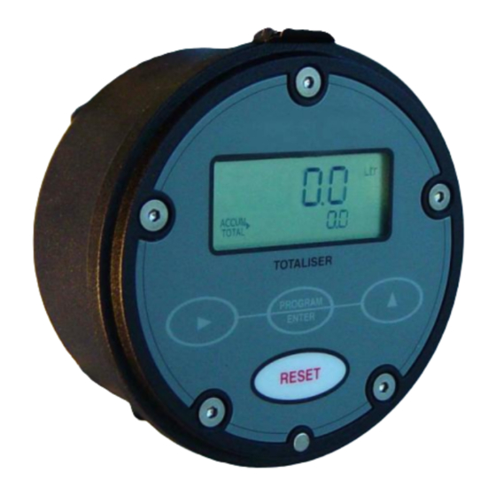
Flow Rate Totaliser
model : RT12..., and Totaliser model : BT11
to w hi c h thi s declaration rel a tes are i n conformit y with the standards noted below :
EN 50014 : 1997 + Amds. 1 & 2 I.S. Intrinsicall y safe electronics (optional) & there are no changes
required to enable compliance to the repl a cement standards EN 60079-0:2006 and EN 60079-1:2004.
EN 50020 : 2002 I.S. Intrinsi c all y safe electroni c s (optional).
In addition & al s o appl y ing to the model EB Batch Controller are the follow ing standards:
EN 60529 : 1991 Degrees of protection (IP)
EN 61326 : 1998 Industrial electromagneti c i m munit y & emi s sions
2002/96/EC Waste electrical & electronic equi p ment (WEEE).
Issued at Taren Point 28
January 2010. Signed for and on behalf of Tri m ec Industries Pt y Ltd.
th
Wayne Fuller, Director
IMBT000-3210
Universal Mount Series
BATTERY TOTALISER
I N S T R U C T I O N
M A N U A L
Advertisement
Table of Contents

Related Manuals for Trimec RT12 Series


Summary of Contents for Trimec RT12 Series
- Page 1 Universal Mount Series BATTERY TOTALISER I N S T R U C T I O N M A N U A L Declaration of Conformity Tri m ec Industries Pt y Ltd declares under sole responsibilit y that the products : Flow Rate Totaliser model : RT12…, and Totaliser model : BT11 to w hi c h thi s declaration rel a tes are i n conformit y with the standards noted below :...
-
Page 2: Table Of Contents
Page 1 TABLE OF CONTENTS INTRODUCTION Description of elements Specifi c ations Overview LCD displays OPERATION Resettable total Accumulative total To review software version No’s press & Keypad function matrix hold program key Battery replacement Processor reset button INSTALLATION Mounting - integral meter mounting - panel mounting - wall / surface mounting... -
Page 3: Introduction
2 Introduction Introduction 3 1.2 Specifications 1. DESCRIPTION OF ELEMENTS Display : 5 digit resettable LCD totaliser 7.5mm ( 0.3”) high with second line 8 digit accumulative total display & text 3.6mm ( 0.15”) high. 3 programmable decimal points with both display lines. Processor Facia Signal Inputs :... -
Page 4: Overview
4 Introduction Operation 5 2. OPERATION 1.3 Overview The instruments are specifically designed for computing & displaying totals from flowmeters 2.1 Resettable Total with pulse or frequency outputs. They are battery powered or can be powered by an external Pressing the RESET key will cause the large 5 digit total to reset to zero. The reset function is 8~24Vdc regulated or I.S. -
Page 5: Installation
Installation 7 INSTALLATION Surface mount footprint 42.6mm ( 1.67 ” ) Mounting Integral meter mounting Use only the 4 special length self tapping screws supplied If using the cable gland supplied carefully drill a 12.5mm (½”) hole at the underside or from the inside rear of Cable diameter range housing... -
Page 6: Un-Powered Sensors
8 Installation Installation 9 3.2 Flowmeter connections ( un-powered sensors ) 3.2 Flowmeter connections ( powered sensors ) For Intrinsically Safe installations refer to I.S. supplement manual. For Intrinsically Safe installations refer to I.S. supplement manual. Namur proximity NOTE : Voltage not to exceed 13.4 Vdc through an approv ed barrier if when using input Reed switch input... -
Page 7: Terminal Designation
10 Installation Installation 11 3.3 Wiring connections - pulse outputs (for I.S. installations refer to I.S. manual.) 3.3 Wiring connections Current Sinking outputs ( NPN ) Current sinking derives its name from the fact that it “sinks current from a load”. The current flows from Terminal designation the load into the appropriate output (terminal 5). - Page 8 12 Programming Programming 13 PROGRAMMING FLOW CHART 4. PROGRAM PARAMETERS 4.1 PIN No. Program Protection The option exists to protect the programmed detail & Accum. Total with a user selected four digit PIN No. ( 0000 represents no PIN protection ). If acti vated the user must input the correct hold Program &...
- Page 9 14 Programming flow chart Troubleshooting 15 5.1 Program detail record If not powered for more than 10 seconds the programmed detail & Accumulated Total will # Display shows software number at all times. be lost from the processor memory, it is advisable to record your programmed detail below.
- Page 10 Index Notes ALPHABETICAL INDEX NPN pulse output 3, 11 Accumulative total Operation Battery condition indicator Overview & Options Battery replacement Battery jumper PIN number protection DC power ( powering ) PNP pulse output 3, 11 Decimal points Processor reset button Displays Programming 12, 13...
Need help?
Do you have a question about the RT12 Series and is the answer not in the manual?
Questions and answers