Table of Contents
Advertisement
USER´S MANUAL
Instructions for Operation, Maintenance
and Installation
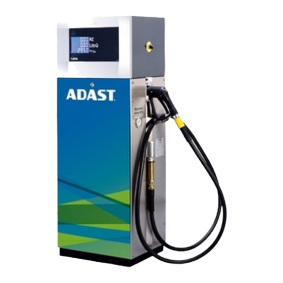
Fuel Dispenser with Suction or Pressure
Pumping System
V-line 899x.xxx
Adast Systems, a.s., 679 04 Adamov No. 496, Czech Republic
T +420 516 519 201, F +420 516 519 102, sales@adastsystems.cz
www.adastsystems.cz
POPULAR
MINOR
OÚ/001/2005/MSS/A
XI/2018
Advertisement
Table of Contents

Related Manuals for Adast Systems MINOR V-line 899 Series


Summary of Contents for Adast Systems MINOR V-line 899 Series
- Page 1 Instructions for Operation, Maintenance and Installation Fuel Dispenser with Suction or Pressure Pumping System POPULAR MINOR V-line 899x.xxx OÚ/001/2005/MSS/A Adast Systems, a.s., 679 04 Adamov No. 496, Czech Republic XI/2018 T +420 516 519 201, F +420 516 519 102, sales@adastsystems.cz www.adastsystems.cz...
-
Page 3: Table Of Contents
USER’S MANUAL V-line 899x.xxx CONTENT INTRODUCTION ......................1 1.1. Used symbols ....................1 1.2. Marking of important information ................1 1.3. Operating, maintenance and installation instructions ........... 2 IMPORTANT NOTICE ....................2 USE ........................4 3.1. The environment of use ..................4 3.2. - Page 4 USER’S MANUAL V-line 899x.xxx 9.5. Dispensing hose ....................45 9.6. Dispensing nozzle ..................... 45 9.7. V-belt of the pump ................... 46 9.8. Dismantling of covers ..................46 9.9. Maintenance instructions for dispenser body parts ............. 47 9.10. Electronic counter .................... 48 10.
-
Page 5: Introduction
USER’S MANUAL V-line 899x.xxx INTRODUCTION The instructions for attendance, maintenance and installation serve the user to gain information on the design, correct attendance, maintenance and safe installation. The information included in the present instructions are mandatory and the manufacturer does not accept any responsibility for any damage due to their non-observance. -
Page 6: Operating, Maintenance And Installation Instructions
USER’S MANUAL V-line 899x.xxx NOTICE! The requirements in this table are based on laws, standards and regulations that deal with the design, installation and operation of dispensers. Failure to meet these requirements may cause a dangerous situation or cause damage to the dispenser. NOTE Best practices, techniques, and methods to ensure correct installation, maintenance and operation of the dispenser. - Page 7 USER’S MANUAL V-line 899x.xxx The information included in the present instructions are mandatory and the manufacturer does not accept any responsibility for any damage due to their non-observance. The dispenser is complicated equipment providing many important functions. Prior to putting into operation tanks and the piping system shall be cleaned and fuel purity shall be checked.
-
Page 8: Use
USER’S MANUAL V-line 899x.xxx Fuel dispensers type series V-line 899x.xxx with electronic counter used for the dispensing of liquid petroleum products - automotive petrol, diesel, kerosene, etc., of alternative liquid fuels (biofuels) - biodiesel (B 10 - B 100) - a mixture of diesel fuel with FAME (Fatty Acid Methyl Ester) and a mixture of automotive petrol with bioethanol (E10 - E 85) (flammable liquids I. - Page 9 USER’S MANUAL V-line 899x.xxx 3.2.1. Gasoline-type fuels “E” stands for specific biocomponents (ethanol) present in petrol (5 % bio-components - bioethanol): “E” stands for specific biocomponents (ethanol) present in petrol (10 % bio-components - bioethanol): “E” stands for specific biocomponents (ethanol) present in petrol (85 % bio-components - bioethanol): 3.2.2.
-
Page 10: Instructions For The Safety Of Work
USER’S MANUAL V-line 899x.xxx FAME according to EN 14214+A1:2014 (100 % bio-components - FAME): INSTRUCTIONS FOR THE SAFETY OF WORK ATTENTION! Any handling open flame is prohibited during fuel filling and smoking is prohibited even in vehicles interior. Also filling vehicle tanks with running motor and any other activities possibly initiating explosion are prohibited! 4.1. -
Page 11: Operation Safety
USER’S MANUAL V-line 899x.xxx 4.2. Operation safety NOTICE! The owner is responsible for the filling station operation and is obliged to follow the course of fuel pumping. In case a customer uses the dispenser incorrectly, the owner shall instruct him about proper use. ... -
Page 12: Hygiene
USER’S MANUAL V-line 899x.xxx 4.3.1. Check of petrol vapor control system – by the Directive 2009/126/EC Check of petrol vapor recovery system Stage II at the dispenser shall be in accordance with Directive 2009/126/ES under the relevant national legislation and regulations applicable in the countries of destination (installation and operation of fuel dispensers). -
Page 13: Description
USER’S MANUAL V-line 899x.xxx DESCRIPTION The fuel dispensers V-line 899x.xxx with electronic counter are used to the dispensing of liquid oil products (inflammable liquids the I. to IV. of danger class. These dispensers enable one-sided or two-sided simultaneous output of 1 or 2 kinds of products. With respect to the application the dispensers of the V-line 899x.xxx type series are supposed to be installed at the following filling stations: V-line 899x.xxx/S –... -
Page 14: Skeleton
USER’S MANUAL V-line 899x.xxx 5.1. Skeleton Skeleton – a self-supporting structure consisting of parts with high anticorrosive resistance. The base of the dispenser is made of steel sheet, zinc-coated and varnished. Internal parts of the skeleton are made of galvanised sheet. Parts of the body with the exception of the door of the hydraulic module and the electronic counter case are made of stainless brushed sheet as a standard. -
Page 15: Hydraulic System Of The Fuel Dispenser
USER’S MANUAL V-line 899x.xxx The covers of the case are hung up on hinges enabling tilting upwards after unlocking and thereby easy access in the case interior. The user’s local preselection keyboard (if required) is located on the case cover as well - an independent keyboard for each dispensing point. 5.1.2. -
Page 16: Hydraulic System Of The Fuel Dispenser V-Line 899X.4X2
USER’S MANUAL V-line 899x.xxx V-belt ELECTROOIL of Pumping monoblock V-belt ELECTROOIL of Vacuum pump Electric motor Motor bracket Motor bracket Blind flange Flange PS G 1 ½“ Ring NBR 70 50 x 3 Belt pulley Valve flange Safety ring ELAFLEX Gasket VD 33/24 Tube –... -
Page 17: Hydraulic System Of The Fuel Dispenser V-Line 899X.6X2
USER’S MANUAL V-line 899x.xxx Hydraulic system of the fuel dispenser V-line 899x.6x2 The integrated hydraulic unit consists of a pumping monoblok (pos. 1) with an integrated large-surface filter (pos. 2), a meter (pos. 3) with integrated magnetic pulse transmitter (pos. 4) connected with the pumping monoblok (pos. - Page 18 USER’S MANUAL V-line 899x.xxx The pumped liquid is supplied from the central submerged pump located directly in the fuel storage tank through the safety breaking valve, spherical check valve and the filter with filtering property of 30 µm for petrol and 30 or 60 µm for Diesel oil. Liquid is discharged from the filter through the meter and the electromagnetic valve to the dispensing hose with the dispensing nozzle at its end.
-
Page 19: Electronics
USER’S MANUAL V-line 899x.xxx 5.3. Electronics The dispenser control shall meet the exacting requirements of simplicity and convenience and depends on the hanging up and lifting of the dispensing nozzle. ADP1/T, ADP2/T, ADP1/L electronic counter of an up-to-date design with central processor board equipped with a high efficient microprocessor. -
Page 20: Vapour Recovery System
USER’S MANUAL V-line 899x.xxx Circuit diagrams for the connection of individual dispenser types to the switchboard of the filling station – see enclosures. 5.3.1. Communication to the control system The dispensers are equipped with ADP1/T, ADP2/T, ADP1/L electronic counters, which are able to communicate to POS Win control systems. - Page 21 USER’S MANUAL V-line 899x.xxx 5.4.1. Description of vapour recovery system Pic.1 ADAST MINOR V-line 8991.623 ADAST POPULAR V-line 8991.423 ADAST POPULAR V-line 8995.423 Pos. 7 – vapour recovery system 5.4.2. System VRC-M Vapour Recovery Control – Mechanical - control the flow of vapor by hydromechanical proportional valve integrated into nozzle (Elaflex GRVP).
- Page 22 USER’S MANUAL V-line 899x.xxx Pic. 2 Function of system VRC-M The vacuum in the VRC-M system is created by piston vacuum pump (Item 2), which is powered via a rubber belt of electric motor of pumping monoblock. For dispensers with pressure system is installed in a compact unit - electric motor with integrated vacuum pump.
- Page 23 USER’S MANUAL V-line 899x.xxx Flexible connecting pipe between the vacuum pump and electromagnetic proportional valve Electromagnetic proportional valve Flexible connecting pipe between the electromagnetic proportional valve and coaxial interpiece Coaxial interpiece for connecting of coaxial delivery hose Coaxial delivery hose Delivery nozzle for vapour recovery Electronic counter ADP1/T, ADP2/T Pic.
- Page 24 USER’S MANUAL V-line 899x.xxx Pic. 3 Pic. 4 System VRC non functional System VRC is functional 5.4.4. System VRC-M with VRMS Vapour Recovery Control - Mechanical - flow control vapor through hydromechanical proportional valve integrated into nozzle (ELAFLEX) controlled system VRMS (Vapor Recovery Monitoring System). Systems VRC-M and VRMS working separately (independently).
- Page 25 USER’S MANUAL V-line 899x.xxx Pic. 6 Pic. 7...
- Page 26 USER’S MANUAL V-line 899x.xxx Electronic connection of unit VAPORIX-Control Terminal block for connection of measuring probe VAPORIX-Flow Terminal block for connection of input power Output – communication line for connecting of unit VAPORIX Master Pulse inlet from the module VAP of electronic counter Out A(B) 1 –...
- Page 27 USER’S MANUAL V-line 899x.xxx Pic. 9 5.4.5. System VRC-E with VRMS Vapour Recovery Control - Mechanical - flow control vapor through hydromechanical proportional valve integrated into nozzle (ELAFLEX) controlled system VRMS (Vapor Recovery Monitoring System). VRC-M Systems and VRMS working separately (independently). Complete system VRC-E + VRMS contains following components (as pic.
- Page 28 USER’S MANUAL V-line 899x.xxx Pic. 15 Pic. 16...
- Page 29 USER’S MANUAL V-line 899x.xxx Pic. 10 Scheme of inputs and outlets of the unit VAPORIX-Control...
- Page 30 USER’S MANUAL V-line 899x.xxx 5.4.6. Function of system VRC with VRMS Function of system VRC-M with VRMS Function of system VRC-M The vacuum in the VRC-M system is created plunger vacuum pump (Item 2), which is powered via a rubber belt electric pumping monoblock. For dispensers with pressure system is installed in a compact unit with integrated electric pump.
- Page 31 USER’S MANUAL V-line 899x.xxx (Item 1) into the duct connected to the vapor inside the storage tank (usually from the lowest octane gasoline). Optimal flow of vapor is dynamically regulated by the proportional hydromechanical valve depending on the actual flow of liquid gasoline trought delivery nozzle. Proper function of vapor recovery is indicated by shining symbol of two arrows (Fig.
- Page 32 USER’S MANUAL V-line 899x.xxx Pic. 11 2. System VRC works out of settled tolerance – first transaction out of the tolerance System status indication on unit VRMS VAPORIX-Control: In the case, that compared values of realised transaction does not match – it means that declinations of real volume flow measured by system VAPORIX from the set value on proportional vapour recovery valve are not in range from 85 % to 115 % exhausted petrol vapours of delivered liquid petrol from the last transaction –...
- Page 33 USER’S MANUAL V-line 899x.xxx Pic. 13 The fault in the revelant system must be fixed by specialised service worker within a period of 7 days (168 hod). 4. VRC system works out of setled tolerance – permanent fault mode – after expire of 7- days time period (168 hours) In the event that the fault of system VRC is not fixed by spealised service worker within a period of 7-days (168 hours) , the functionality of the fuel dispenser will be permanently...
-
Page 34: Signalling Of Dispenser Conditions (So)
USER’S MANUAL V-line 899x.xxx 5.5. Signalling of dispenser conditions (SO) On Client’s special requirement the fuel dispenser can be equipped with a red signal light, which gives information to the customer and the operator about the present dispenser condition – the dispenser is blocked or ready for fuel filling. - Page 35 USER’S MANUAL V-line 899x.xxx Basic sensed unit 0,01 dm Number of impulses per 1 dm Permissible deviation of sensed volume +/-1 impulse, i.e. 0,01 dm Price displayed 6 digits with the setting of digit position Volume displayed 6 digits with the setting of digit position Unit price displayed 4 digits with the setting of digit position electromechanical - 7 digits...
- Page 36 USER’S MANUAL V-line 899x.xxx Operating flowrate by dispensing from one nozzle – connection of submersible pump with min. flow rate 120 dm .min with min. 120 ± 12 dm .min 120 ± 12 dm .min dynamic operating pressure 0,22 MPa on inlet into the dispenser – pressure system Q Min.
- Page 37 USER’S MANUAL V-line 899x.xxx V-line V-line 6.1.7. Technical parameters of the fuel dispenser 8991.6x/S; /P 8991.4x/S; /P Max. rate of flow Q 40 dm .min 40 dm .min Min. rate of flow Q 4 dm .min 4 dm .min Pumping capacity at suction head –45 kPa Q 40 ±...
- Page 38 USER’S MANUAL V-line 899x.xxx V-line V-line 6.1.10. Technical parameters of the fuel dispenser 8994.6x2/S; /P 8994.4x2/S; /P Max. rate of flow Q 40 dm .min 40 dm .min Min. rate of flow Q 4 dm .min 4 dm .min Pumping capacity at suction head –45 kPa Q 40 ±...
- Page 39 USER’S MANUAL V-line 899x.xxx 6.1.14. Technical parameters of the fuel dispenser V-line 8998.6x/S; /P, V-line 8998.4x/S; /P dispensing point dispensing point Max. rate of flow Q 80 dm .min 80 dm .min Min. rate of flow Q 5 dm .min 5 dm .min Pumping capacity at suction head –45 kPa Q...
-
Page 40: Basic Parameters For The Vegetable And Mineral Oils With Dynamic Viscosity Up To 1000 Mpa.s
USER’S MANUAL V-line 899x.xxx 6.1.18. Technical parameters of the fuel V-line 8997.6x3/S; /P/70 V-line 8997.6x3/LC/S; /P/70 dispenser Max. rate of flow Q 70 dm .min Min. rate of flow Q 5 dm .min Pumping capacity at suction head –45 kPa Q 70 ±... - Page 41 USER’S MANUAL V-line 899x.xxx Average service life = 5 years ) Max. flowrate Q = 40, 60, 70, 80 dm .min and min. flow rate Q = 4, 5 dm .min – extreme values of rate of flow in which can be operate the measuring system of the fuel dispenser – parameters Q and Q given in a certificate about homologation of the meter type.
-
Page 42: Identification
All manufactured and delivered dispensers are provided with a rating plate, which includes the following data and is located on a visible point of the dispenser body: Measuring device manufacturer and address Adast Systems, a.s., CZ – 679 04 Adamov 496 Name of measuring device Fuel dispenser... -
Page 43: Operation
USER’S MANUAL V-line 899x.xxx OPERATION ATTENTION! When pumping liquid fuels it is forbidden to smoke and handle open fire! No smoking applies to people inside the car! It is forbidden to pump into the vehicle tanks while the engine is running ... -
Page 44: Attendance
USER’S MANUAL V-line 899x.xxx 8.2. Attendance Only simple steps are used to attend the dispenser. It is up to the customer’s decision what fuel he is going to fill. The electronic counter is activated by lifting the dispensing nozzle, test of proper function of the counter, automatic switching on of the pump and opening of electromagnetic valves are performed. -
Page 45: Functions Of Kl-Maninf Manager And Kl-Serinf Service Keyboards
USER’S MANUAL V-line 899x.xxx 1.a) Preselect the required quantity to be dispensed according to the price by keys identified 5 (for example) and 10 in arbitrary sequence up to the amount of money level. The preselected quantity to be dispensed is displayed on the price display. In case of invalid option deselect it by the "reset"... - Page 46 USER’S MANUAL V-line 899x.xxx the number of side for which the unit price is being set ("1" ... A side, "2" ... B side) is displayed – on the first line of displays (i.e. on the line of total price) the number of nozzle for which the unit price is being set is displayed on the second line of –...
-
Page 47: Maintenance Of A Dispenser And Its Individual Operating Units
USER’S MANUAL V-line 899x.xxx to the price totalizer displays of the next dispensing nozzles by repeated depressing the "–" key or by lifting the relevant nozzle). 6. Terminate the scanning of electronic totalizers by depressing the "0" key and in case the thermal and electronic calibration are activated, transition in the display mode of their setting occurs. -
Page 48: Pumping Monoblock
USER’S MANUAL V-line 899x.xxx ATTENTION! Before performing all service and maintenance work on mechanical, hydraulic and electrical components, it is always necessary to securely disconnect the power supply to the dispenser and ensure reliable re-connection during maintenance! Only approved components may be used when replacing parts. All parts subject to ... -
Page 49: Piston Flowmeter
USER’S MANUAL V-line 899x.xxx 5. Carry out the reassembly. Prior to the reassembly check the condition of the O-rings on the insertion with the integrated check valve and in the filter cover. Replace them if necessary. Faulty O-rings can result in level drop or air intake. 6. -
Page 50: V-Belt Of The Pump
USER’S MANUAL V-line 899x.xxx hose adapter while taking care not to lose the screen located in the nozzle. The screen shall be cleaned regularly because the clogged screen may result in substantial reduction of fuel flow. 9.7. V-belt of the pump A swivelling bracket of the el. -
Page 51: Maintenance Instructions For Dispenser Body Parts
USER’S MANUAL V-line 899x.xxx Dismantling of the vacuum pump set It is carried out by loosening four M6 bolts fixing the pump to the bracket. The vacuum pump bracket can be dismounted by loosening the two M8 nuts used also for the belt tightening control. Prior to the vacuum pump removal disconnect both the suction and discharge piping by loosening two hollow bolts. -
Page 52: Electronic Counter
USER’S MANUAL V-line 899x.xxx Recommended time interval for the maintenance of stainless body parts: ATTENTION! DO NOT WASH STAINLESS STEEL SHEETS BY WATER OR EVEN SURFACTANT!! Recommended procedure for stainless steel sheets: Washing of parts by thorough cleaning of salt residues, dust and grease followed by the renewal of protective coating on body parts - by special agent for the protection of stainless steel sheet - once a month. -
Page 53: Transport
The customer shall agree to the method of dispenser transport from the manufacturer in the contract. In case Adast Systems, a.s. provides the transport for the customer, the product will be delivered to the agreed destination. The manufacturer possesses the necessary knowledge of handling and transportation methods. -
Page 54: Hydraulic Part
USER’S MANUAL V-line 899x.xxx Prior to the installation the organisation shall perform the inspection of used power and communication cables. When the dispenser is installed, they shall check the tightness, function of hydraulic equipment of the dispenser, supply piping and fittings. They also check power and communication cables including their lines and fixing. - Page 55 USER’S MANUAL V-line 899x.xxx Greater Pressure system – submersible pump in the tank – than 35 Table 2 – Operating flow rate of the fuel dispenser in relation on the fuel storage tanks parameters for hydraulic unit with Q = 80 dm .min = 130 dm .min...
- Page 56 USER’S MANUAL V-line 899x.xxx 13.1.2. Installation at the filling station with overground (aboveground) tanks A safety relief check valve (PZV), opening at vacuum pressure Hs = – 0,03 MPa max. induced by dispenser pump, shall be installed in the suction piping (PT) connecting the dispenser and the storage tank.
-
Page 57: Mounting Of Spring Of The Spring Hinge
USER’S MANUAL V-line 899x.xxx Fig. 3 – Example of the suction piping design for the connection of the fuel dispenser to the overground tank Fig. 4 Connecting of pipeline output from air separator (OT) in case of connecting fuel dispenser to overground tank. 13.2. -
Page 58: Wiring
USER’S MANUAL V-line 899x.xxx 13.3. Wiring ATTENTION! Emergency switching off! It shall be enabled to switch off the filling equipment from one point, which is accessible anytime. The electric equipment situated in the explosion hazard area can be switched off by means of the emergency breaker located outside the explosion hazard area. The switch for normal operation can be also used as emergency breaker. -
Page 59: Packing And Storage
USER’S MANUAL V-line 899x.xxx PACKING AND STORAGE 14.1. Packing The packing of dispensers differs in dependence on the point of destination. Dispensers for home market are packed up in bubble wrap, while cardboard wrapping is mostly used for abroad. On preliminary agreement of the customer the dispensers delivered abroad can be also packed up in bubble wrap or other similar packing. -
Page 60: Spare Parts Catalogue
USER’S MANUAL V-line 899x.xxx Defects from faulty low power wiring at the filling station, faulty wiring of communication cables – especially as far as interference is concerned missing UPS (ON LINE) - mains supply standardised voltage values: U nominal ±15 % with frequency 50 Hz The guarantee does not cover consumable supplies: filter bushings, V-belts, etc. -
Page 61: Enclosures
USER’S MANUAL V-line 899x.xxx ENCLOSURES Enclosure No. 1 Main dimensions of V-line 899x.xx2/S dispensers Enclosure No. 2 Main dimensions of V-line 899x.xx2/P dispensers Main dimensions of V-line 899x.6x3/S, /P, V-line 899x.6x4 /S,/P; V-line Enclosure No. 3 899x.6x3/S, /P/CA dispensers Main dimensions of V-line 899x.6x3/LC/S, /P; V-line 899x.xx4/LC/S,/P/CA Enclosure No. - Page 62 USER’S MANUAL V-line 899x.xxx Connection of V-line 899x.6x3/P and V-line 899x.6x3/LC/P dispensers with vapour Enclosure No. 28 recovery system and with ADP1/L counter to the filling station switchboard Connection of V-line 899x.6x3/P and V-line 899x.6x3/LC/P dispensers without Enclosure No. 29 vapour recovery system with ADP1/L counter to the filling station switchboard Connection of V-line 899x.6x3/S and V-line 899x.6x3/LC/S dispensers with ADP1/T Enclosure No.
- Page 63 Type identification on the rating plate of V-line 899x.xxx dispenser Enclosure No. 52 Type identification on the rating plate of V-line 899x.xxx/CA dispenser Enclosure No. 53 Adast Systems, a.s., 679 04 ADAMOV No. 496, Czech Republic Regarding continuous development the producer stipulates the right to pursue technical changes!
- Page 65 USER’S MANUAL V-line 899x.xxx Main dimensions of V-line 899x.xx2/S dispensers Width of all fuel dispensers is 410 mm Enclosure no. 1...
- Page 66 USER’S MANUAL V-line 899x.xxx Main dimensions of V-line 899x.xx2/P dispensers Width of all fuel dispensers is 410 mm Enclosure no. 2...
- Page 67 USER’S MANUAL V-line 899x.xxx Main dimensions of V-line 899x.6x3/S, /P, V-line 899x.6x4 /S,/P; V-line 899x.6x3/S, /P/CA dispensers Width of all fuel dispensers is 410 mm Enclosure no. 3...
- Page 68 USER’S MANUAL V-line 899x.xxx Main dimensions of V-line 899x.6x3/LC/S, /P; V-line 899x.6x3/LC/S, /P/CA dispensers Width of all fuel dispensers is 410 mm. Enclosure no. 4...
- Page 69 USER’S MANUAL V-line 899x.xxx View of dispensers V-line 899x.4x2 series Enclosure no. 5...
- Page 70 USER’S MANUAL V-line 899x.xxx View of dispensers V-line 899x.6x3 series View of dispensers V-line 899x.6x3/CA series with Tankautomat ADAMAT Enclosure no. 6...
- Page 71 USER’S MANUAL V-line 899x.xxx View of dispensers V-line 899x.6x3/OIL/CA series with Tankautomat ADAMAT Enclosure no. 7...
- Page 72 USER’S MANUAL V-line 899x.xxx Minimum distance betwen the side wal of the fuel dispenser and steady barrier at the location on the filling station Enclosure no. 8...
- Page 73 USER’S MANUAL V-line 899x.xxx Dispensing nozzle positions during fuel dispensing 1. Correct position of dispensing nozzle during filling The dispensing nozzle is almost in the horizontal position, the ball does not prevent from air passing, the fuel flows through 2. Incorrect position of dispensing nozzle during filling The dispensing nozzle is diverted from the horizontal plane (drawn position).
- Page 74 USER’S MANUAL V-line 899x.xxx Conditions of wiring and operation of UPS for feeding a control system and electronic part of V–line dispensers 1. All the cooperating electronic circuits of the control system and dispensers must be connected to the UPS and for this point of view they are considered as a closed electronic unit.
- Page 75 USER’S MANUAL V-line 899x.xxx Installation dimensions of V-line 8990.xx2/P, 8991.xx2/S, /P, 8995.xx2/S, /P, 8997.xx2/S, /P, 8999.xx2/S, /P dispensers Enclosure no. 11...
- Page 76 USER’S MANUAL V-line 899x.xxx Installation dimensions of V-line 8990.xx2/S, 8993.xx2/S, /P, 8994.xx2/S, /P, 8996.xx2/S, /P, 8998.xx2/S, /P dispensers Enclosure no. 12...
- Page 77 USER’S MANUAL V-line 899x.xxx Installation dimensions of V-line 899x.6x3/S, /P; V-line 899x.6x3/S, /P/CA dispensers Enclosure no. 13...
- Page 78 USER’S MANUAL V-line 899x.xxx Installation dimensions of V-line 899x.6x3/LC/S, V-line 899x.6x3/LC/S/CA dispensers Enclosure no. 14...
- Page 79 USER’S MANUAL V-line 899x.xxx Installation dimensions of V-line 899x.6x3/LC/P, V-line 899x.6x3/LC/P/CA dispensers Connection with ball valve Connection without ball valve Enclosure no. 15...
- Page 80 USER’S MANUAL V-line 899x.xxx V-line dimensions of V-line 899x.6x4/S, /P dispensers Enclosure no. 16...
- Page 81 USER’S MANUAL V-line 899x.xxx Connection of V-line 899x.xxx/S dispensers Connection for Connection for Q = 40 dm .min Q = 2 x 40 dm .min Q = 1 х 80; 100, 110; 120; 130; 150 dm .min Connection of satelite outlet Q = 1 х...
- Page 82 USER’S MANUAL V-line 899x.xxx Connection of V-line 899x.xxx/P dispensers Q = 1 x 40; 2 x 40; 1 х 80; 110; 120; 130; 150 dm .min Enclosure no. 18...
- Page 83 USER’S MANUAL V-line 899x.xxx Connection of V-line 899x.xxx/P dispenser - „SUPERMAX“ Q = 130 dm .min , Q = 150 dm .min Enclosure no. 19...
- Page 84 USER’S MANUAL V-line 899x.xxx Connection of satellite outlet at the V-line 899x.xxx/S and 899x.xxx/P dispensers Enclosure no. 20...
- Page 85 USER’S MANUAL V-line 899x.xxx Connection of V-line 899x.xxx/S dispensers to the filling station switchboard Enclosure no. 21...
- Page 86 USER’S MANUAL V-line 899x.xxx Connection of V-line 8991.xx2/P, 8993.xx2/P, 8995.xx2/P dispensers with vapour recovery system to the filling station switchboard Enclosure no. 22...
- Page 87 USER’S MANUAL V-line 899x.xxx Connection of V-line 8994.xxx/P, 8996.xxx/P dispensers with vapour recovery system to the filling station switchboard Enclosure no. 23...
- Page 88 USER’S MANUAL V-line 899x.xxx Connection of V-line 8990.xx2/P, 8991.xx2/P, 8993.xx2/P, 8995.xx2/P, 8997.xx2/P, 8999.xx2/P dispensers without vapour recovery system to the filling station switchboard Enclosure no. 24...
- Page 89 USER’S MANUAL V-line 899x.xxx Connection of V-line 8994.xxx/P, 8996.xxx/P, 8998.xxx/P dispensers without vapour recovery system to the filling station switchboard Enclosure no. 25...
- Page 90 USER’S MANUAL V-line 899x.xxx Connection of V-line 899x.xxx dispensers with satellite to the filling station switchboard Enclosure no. 26...
- Page 91 USER’S MANUAL V-line 899x.xxx Connection of V-line 899x.6x3/S and V-line 899x.6x3/LC/S dispensers with ADP1/L counter to the filling station switchboard Enclosure no. 27...
- Page 92 USER’S MANUAL V-line 899x.xxx Connection of V-line 899x.6x3/P and V-line 899x.6x3/LC/P dispensers with vapour recovery system and with ADP1/L counter to the filling station switchboard Enclosure no. 28...
- Page 93 USER’S MANUAL V-line 899x.xxx Connection of V-line 899x.6x3/P and V-line 899x.6x3/LC/P dispensers without vapour recovery system with ADP1/L counter to the filling station switchboard Enclosure no. 29...
- Page 94 USER’S MANUAL V-line 899x.xxx Connection of V-line 899x.6x3/S and V-line 899x.6x3/LC/S dispensers with ADP1/T counter to the filling station switchboard Enclosure no. 30...
- Page 95 USER’S MANUAL V-line 899x.xxx Connection of V-line 899x.6x3/P and V-line 899x.6x3/LC/P dispensers with vapour recovery system and with ADP1/T counter to the filling station switchboard Enclosure no. 31...
- Page 96 USER’S MANUAL V-line 899x.xxx Connection of V-line 899x.6x3/P and V-line 899x.6x3/LC/P dispensers without vapour recovery system and with ADP1/T counter to the filling station switchboard Enclosure no. 32...
- Page 97 USER’S MANUAL V-line 899x.xxx Connection of V-line 899x.6x3/S dispenser without the conduit box to the filling station switchboard Enclosure no. 33...
- Page 98 USER’S MANUAL V-line 899x.xxx Connection of V-line 899x.6x3/P dispenser without the conduit box to the filling station switchboard Enclosure no. 34...
- Page 99 USER’S MANUAL V-line 899x.xxx Connection of V-line 8991.x83/CA, V-line 8991.x83/LC/CA and V-line 8997.x83/CA, V-line 8997.x83/LC/ CA dispensers to the filling station switchboard Enclosure no. 35...
- Page 100 USER’S MANUAL V-line 899x.xxx Connection of V - line 899x.6x4/S dispensers with mechanical counter to the filling station switchboard Enclosure no. 36...
- Page 101 USER’S MANUAL V-line 899x.xxx Connection of V-line 899x.6x4/P dispensers without vapour recovery system with mechanical counter to the filling station switchboard Enclosure no. 37...
- Page 102 USER’S MANUAL V-line 899x.xxx Connection of V-line 899x.xxx dispensers with vapour recovery system with automatic control system VRMS (Vapour Recovery Monitoring System). Enclosure no. 38...
- Page 103 USER’S MANUAL V-line 899x.xxx Connection of the fuel dispenser heating to the filling station switchboard (valid only for the fuel dispenser with electronic case heating Enclosure no. 39...
- Page 104 USER’S MANUAL V-line 899x.xxx Connection of the magnetic pulse transmitter ME 01-05, ME 01-05-05 and ADAST 40 or MTX 075 to the electronic counter ADP1/L - connector X1 Magnetic pulse transmitter Magnetic pulse transmitter Magnetic pulse transmitter Magnetic pulse transmitter ME 01-05 ME-01-05-05 ADAST 40...
- Page 105 USER’S MANUAL V-line 899x.xxx Connection of the magnetic pulse transmitter ME 01-05, ME 01-05-05 and ADAST 40 or MTX 075 to the electronic counter ADP1/T, ADP2/T - connector X2 Enclosure no. 41...
- Page 106 USER’S MANUAL V-line 899x.xxx A location scheme official marks on the flowmeter M 403.25P for mechanical calibration A location scheme official marks on the flowmeter M 403.25P/1 for mechanical calibration Enclosure no. 42...
- Page 107 USER’S MANUAL V-line 899x.xxx A location scheme official marks on the flowmeter M 403.xxEP for electronic calibration A location scheme official marks on the flowmeter M 403.xxEP/1 for electronic calibration Enclosure no. 43...
- Page 108 USER’S MANUAL V-line 899x.xxx A location scheme official marks on the pumping unit P641.xxx/2/SS A location scheme official marks on the temperature sensor PT 100 (Just if ATC conversion function is activated) Enclosure no. 44...
- Page 109 USER’S MANUAL V-line 899x.xxx A location scheme marks official on the temperature sensor PT 100 – fuel dispenser connected to the central pressure system A location scheme official marks on ADP1/L electronic calculator Enclosure no. 45...
- Page 110 USER’S MANUAL V-line 899x.xxx A location scheme official marks on ADP1/T а ADP2/T L electronic calculator A location scheme verification marks on electromagnetic total counter for single-sided fuel dispensers Enclosure no. 46...
- Page 111 USER’S MANUAL V-line 899x.xxx A location scheme verification marks on electromagnetic total counter (case version 2017) Enclosure no. 47...
- Page 112 USER’S MANUAL V-line 899x.xxx Hazardous zones of fuel dispensers V-line 899x.xxx series Hazardous zones both inside and outside the fuel dispenser have been defined according to EN 13617-1+ A1. Fuel dispenser V-line 899x.6х2: The inner space of the fuel dispenser hydraulic housing – ZONE 1. The inner space of the fuel dispenser column –...
- Page 113 USER’S MANUAL V-line 899x.xxx Hazardous zones of fuel dispensers V-line 899х.6х2 Hazardous zones of fuel dispensers V-line 8991.6х2, V-line 8995.6х2, V-line 8997.6х2, V-ine 8999.6х2 Hazardous zones of fuel dispensers V-line 8990.6х2, V-line 8993.6х2, V-line 8994.6х2, V-line 8996.6х2, V-line 8998.6х2 Enclosure no. 49...
- Page 114 USER’S MANUAL V-line 899x.xxx Hazardous zones of fuel dispensers V-line 899х.4х2 Hazardous zones of fuel dispensers V-line 8991.4х2, V-line 8995.4х2, V-line 8997.4х2, V-line 8999.4х2 Hazardous zones of fuel dispensers V-line 8990.4х2, V-line 8993.4х2, V-line 8994.4х2, V-line 8996.4х2, V-line 8998.4х2 Enclosure no. 50...
- Page 115 USER’S MANUAL V-line 899x.xxx Hazardous zones of fuel dispensers V-line 899х.6х3 Hazardous zones of fuel dispensers V-line 8991.6х3, V-line 8997.6х3, Enclosure no. 51...
- Page 116 USER’S MANUAL V-line 899x.xxx Type identification on the rating plate of V-line 899x.xxx dispenser 1 - mechanické 2 - ADP - elektronické 3 - Quitec - elektronické 4 - PE - elektronické 5 - GVR (Logitron) - elektronické 6 - Precis - elektronické 0 –...
- Page 117 USER’S MANUAL V-line 899x.xxx Type identification on the rating plate of V-line 899x.xxx/CA dispenser 0 – MONO – SUPERMAX Q = 110, 120, 130, 150 l/min 1 – MONO Q = 40, 60 l/ 3 – DUO Q = 2 x 40, 40 +110, 40 + 120 l/min 4 –...
Need help?
Do you have a question about the MINOR V-line 899 Series and is the answer not in the manual?
Questions and answers