
Subscribe to Our Youtube Channel
Summary of Contents for Kentec Electronics Taktis K772
- Page 1 Fire Control Panel Additional Boards Installation Manual Man-1170EN Rev.01 *Man-1170* Additional Boards Installation Manual...
- Page 2 Using This Manual • Related Documentation • If You Need Help • Contacting Kentec Electronics Using This Manual The following sections provide instructions for installing, testing and troubleshooting the Taktis Fire Alarm Control Panel Boards: Section A: Preface Provides document conventions.
- Page 3 • SRI parts are loan items and are not available for resale. • At all times, Kentec Electronics. retains the title of SRI parts supplied, as detailed in Section 7.4 of the Terms and Conditions of Sale. • All SRI parts must be returned to the Customer Service department of Kentec Electronics within 14 days of delivery.
- Page 4 Kentec Electronics are under no liability if the repaired or replaced components are found to have failed due to fair wear and tear, wilful damage, negligence, abnormal working conditions, misuse or alteration or repair without approval or failure to follow the sellers instructions.
-
Page 5: Table Of Contents
Contents i Section 1 Overview ..........................1 Additional Board Layout ..........................2 Main Back Board Layout ..........................3 Extension Board Layout ..........................4 Label Sheet ..............................5 Section 2 Installation ........................6 General Installation Checklist........................6 Before You Begin ............................6 Installing An Additional Board ........................7 Field Terminal Assignments .......................... -
Page 6: Overview
Overview 1 Section 1 Overview The Additional Boards further enhance the versatility of the fire alarm system. The Additional Boards available and their typical applications are as follows: Model Name Typical Application Used in applications such as LED floor plan mimic 16 Channel I/O Board drivers or to receive inputs from plant alarms or other related systems. -
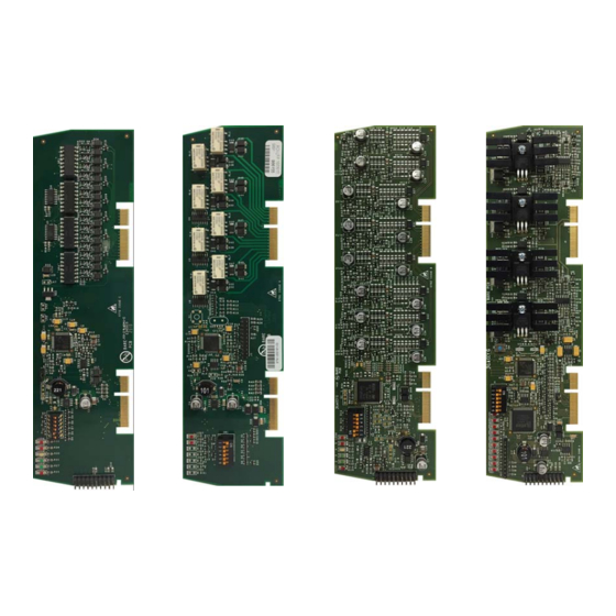
Page 7: Additional Board Layout
Overview 1 Additional Board Layout The figure below shows common features associated with all additional boards. Familiarise yourself with these fea- tures prior to the installation. Figure 1-5 Additional Board Common Features 16 Channel I/O card shown in this example. Description Board slot connection Address dip switch... -
Page 8: Main Back Board Layout
Overview 1 Main Back Board Layout Fitted to all versions of the Fire Control Panel. The figure below shows the panel main back board layout identifying elements associated with the installation of additional boards. Figure 1-6 Main back board features Description Description Board Slot A... -
Page 9: Extension Board Layout
Overview 1 Extension Board Layout Fitted to 2 to 16 loop versions of the panel only. The figure below shows the extension board associated with 2 to 16 loop versions of the panel. Where appropriate, familiarise yourself with these elements prior to the installation. Figure 1-7 Main back board features Description... -
Page 10: Label Sheet
Overview 1 Label Sheet With each additional board are supplied self-adhesive labels. The labels can be stuck to the board (over existing terminal designations) providing terminal designations associated with the additional board fitted. Use the appropriate label associated with the Additional Board. Figure 1-8 Label sheet (not to scale) 4 Way... -
Page 11: Installation
Installation 2 Section 2 Installation This section provides instructions for installing and addressing the additional boards. For general installation guid- ance refer to the main panel Installation Instructions. General Installation Checklist To complete the installation: Retrieve the panel configuration file. Remove the additional card(s) packaging and check the contents. -
Page 12: Installing An Additional Board
Installation 2 Installing An Additional Board The following steps cover removing the main board cover and fitting an additional board. This process is the same from for 2-8 Loop and 2-16 Loop versions of the panel. 13. Remove power at the mains and disconnect standby-batteries prior to performing the circuit board installation. -
Page 13: Field Terminal Assignments
Installation 2 Field Terminal Assignments Circuit board slot positions on the Main Back Board correspond to specific field terminal locations on the Main Back Board: The table below shows slots available for additional boards: Slot System Board System Board 16 Channel 8-Way 8-Way 4-Way... - Page 14 Installation 2 Figure 2-5 Board Slot D Figure 2-6 Board Slot E Man-1170EN Rev.01 Additional Boards Installation Manual...
- Page 15 Installation 2 Figure 2-7 Board Slot F Man-1170EN Rev.01 Additional Boards Installation Manual...
-
Page 16: Extension Board Field Terminal Assignments
Installation 2 Extension Board Field Terminal Assignments Circuit board slot positions on the Extension Board correspond to specific field terminal locations on the Extension Board: The table below shows slots available for additional boards: Slot System Board System Board 16 Channel 8-Way 8-Way 4-Way... - Page 17 Installation 2 Figure 2-9 Additional Board Slot H Figure 2-10 Additional Board Slot J Note: For figment rotate sticker label 90 degrees. Man-1170EN Rev.01 Additional Boards Installation Manual...
- Page 18 Installation 2 Figure 2-11 Additional Board Slot K Note: For figment rotate sticker label 90 degrees. Man-1170EN Rev.01 Additional Boards Installation Manual...
-
Page 19: Setting The Address
Setting the Address 3 Section 3 Setting the Address Each Additional Board must have its DIP switch set between address 1 and 32 before being fitted to the Main Back Board. The numeric order of the address setting between circuit boards does not impact operation but, each circuit board must be assigned a unique address. -
Page 20: 16 Channel I/O Board
16 Channel I/O Board 4 Section 4 16 Channel I/O Board The 16 channel I/O (Input/Output) board may occupy one or more slots of the panel main back board or expansion board. Each channel may be configured as an input or an output. Each port provides a means to receive volt free contact inputs or it can provide open collector outputs for control panels. -
Page 21: Inputs
16 Channel I/O Board 4 Inputs • Inputs to the I/O board are optically isolated and are activated by connecting any of the terminals marked 0V to the input via a contact with a resistance no greater than 500 ohms. The current switched by the contact will be a maximum of 3 milliamps. -
Page 22: 8-Way Relay Board
8-Way Relay Board 5 Section 5 8-Way Relay Board The 8-Way relay board may occupy one or more slots of the panel main back board or expansion board. It provides a means to provide programmable, volt free normally open contact outputs. Each channel may be configurable as normally open or normally closed (active/inverted). -
Page 23: 8-Way Conventional Board
8-Way Conventional Board 6 Section 6 8-Way Conventional Board The 8-Way Relay Board may occupy one or more slots of the panel main back board or expansion board. It provides eight detection circuits which are compatible with a range of detection devices. Figure 6-1 8-Way Conventional Board Description... -
Page 24: Detection Inputs
8-Way Conventional Board 6 Detection Inputs • Detection inputs provide current limited, resetting power suitable for most types of conventional detectors. Monitoring is achieved by fitting a 6K8 end of line resistor at the last device on the detection line. Power is removed from all detection lines for 5 seconds when the reset button at the main fire control panel is pressed, thus resetting any activated detectors. -
Page 25: 4-Way Sounder Board
4-Way Sounder Board 7 Section 7 4-Way Sounder Board The 4-Way Sounder Board may occupy one or more slots of the panel main back board or expansion board. It pro- vides a means to connect sounders, strobes or other devices requiring a nominal 24V DC supply to radial wiring from the control panel. -
Page 26: Sounder Outputs
4-Way Sounder Board 7 Sounder Outputs • Utilising Class A wiring 2 sounder circuits are possible. • Utilising Class B wiring 4 sounder circuits are possible. • The sounder outputs are open and short circuit monitored by fitting a 10K 0.25W resistor across the last device fitted to the field wiring (Class B). -
Page 27: Battery Consumption
Battery Consumption A Appendix A Battery Consumption All Additional Boards The effect of the power consumption of relay boards must be considered when calculating battery standby. Each board has a quiescent current consumption of 10 mA which will require (24 X 0.01A) + 25% = 0.3Ah of extra battery capacity per 24 hour standby period. -
Page 28: Specifications
Specifications B Appendix B Specifications 16 Channel I/O • Part number: K772 • Supply voltage range: 21V to 30V DC • Quiescent current consumption: 15mA • Current per input: 3mA • Current per output: Max 100mA per output OR 500mA across bank of 8 outputs (500mA for 1-8, 500mA for 9-16). •...
Need help?
Do you have a question about the Taktis K772 and is the answer not in the manual?
Questions and answers