Table of Contents
Advertisement
Quick Links
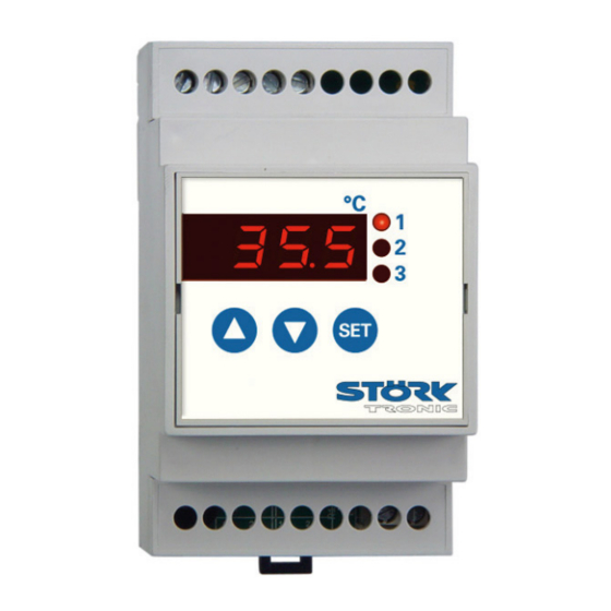
ST46-IN1KAR.112
Controller for cooling applications
Order number 900237.030
As of: 26.01.2017, Software V1.0
Wiring diagram
Product description
The controller ST46-IN1KAR.112 is intended for the assembly on DIN rail, which allows easy installation in the
switch gear cabinet. It has two analogue inputs for PTC sensors and four switching exits. The functions of the re-
lays can be freely selected, whereas various applications with only one controller are possible. The controller, for
example, can operate with two coolers if the evaporator sensor is parameterized as sensor for a second refrigerat-
ing chamber. The LEDs indicate the status of the control exits. The controller is supplied with 230V AC.
Networking of the controller takes place via ST Bus interface.
Sensor: PTC
Range: - 50 ... 130 °C
Housing size (L x W x H): 95 x 53 x 59mm
Installation: Clip-on mounting on DIN-Rail 35 x 7,5mm
Connector: screw terminal
Order no. 900237.030
V1.0
Page 1
Advertisement
Table of Contents

Related Manuals for Störk-Tronic ST46-IN1KAR.112


Summary of Contents for Störk-Tronic ST46-IN1KAR.112
- Page 1 Wiring diagram Product description The controller ST46-IN1KAR.112 is intended for the assembly on DIN rail, which allows easy installation in the switch gear cabinet. It has two analogue inputs for PTC sensors and four switching exits. The functions of the re- lays can be freely selected, whereas various applications with only one controller are possible.
- Page 2 Order no. 900237.030 V1.0 Page 2...
- Page 3 SOFTWARE COOLING CONTROLLER ST46-xxx.112 Order no. 900237.030 V1.0 Page 3...
-
Page 4: General Information
GENERAL INFORMATION CONTROL KEYS The ST……112 controllers are designed for general use in refrigerating plants. Depending on the existing hardware, up to four temperature sensors can be connected. These can either be used for capturing the cold store temperature, evaporator temperature, super-frost core temperature, the temperature of a second control circuit or the temperature of the condenser. -
Page 5: Network Address
PARAMETERISATION NETWORK ADDRESS Parameterisation of the cooling controller is done in Under code word you can set a the factory or during commissioning of a cold store by network address. This is required for qualified staff. Wrong or inappropriate commissioning networked systems. - Page 6 Alarms Buttons and switching inputs Control circuits 1 Defrosting control circuits 1 Fan control circuits 1 Temperature sensors Pre-defined sets of parameters Networking and display Week timer Relay contacts and lamps ...
- Page 7 Alarms (password-protected) Para- Description of function Setting range Values meter default Assignment of alarm sensors, detailed 0: none description of sensors in parameters 1: Sensor F1 through 2: Sensor F2 3: Sensor F3 4: Sensor F4 5: weighted mean value from F1 and F2 ...
- Page 8 Buttons and switching inputs (password-protected) Para- Description of function Setting range Values meter default Function button T1 0: without function 1:controller on/standby 2:defrosting request 3:acknowledge alarm 4:relay function light 1, not active in standby 5:relay function light 1, regardless of standby 6:relay function light 2, not active in standby 7:relay function light 2, regardless of standby 8:relay function window heating, not active in standby...
-
Page 9: Control Circuit
Para- Description of function Setting range Values meter default Function of external switching 0:without function input E1 1:controller on/standby 2:high-pressure alarm (see 3:low-pressure alarm (see 4:door contact (light on, fan off, see 5:relay function A (light 1), not active in standby 6:relay function A (light 1), regardless of standby 7:relay function B (light 2), not active in standby 8:relay function B (light 2), regardless of standby... - Page 10 Para- Description of function Setting range Values meter default Switching mode 0: heating 1: refrigerating Hysteresis 0.1...15.0°C Hysteresis mode 0: symmetrical 1: one-sided Upper setpoint limit ...+99°C 50.0 Lower setpoint limit -99°C... -50.0 ...
-
Page 11: Fan Control Circuit
Para- Description of function Setting range Values meter default Delay of start of defrosting after compressor 0 ... 900 sec. Dripping time 0 ... 15 min. Stop delay drip tray heating 0 ... 60 min. ... -
Page 12: Temperature Sensors
Temperature sensors (password-protected) Para- Description of function Setting range Values meter default Mains frequency 0: 50Hz 1: 60Hz Act. value sensor F1 Measured value, not adjustable Calibration sensor F1 (act. value correction) -20...+20.0°C Weighting factor sensor F1 0.50...1.50 1.00 ... - Page 13 Pre-defined parameter sets (password-protected) Para- Description of function Setting range Values meter default Parameter set Password for entering level selection (in -99 ... 999 display Password of parameter level -99 ... 999 Parameter can only be viewed and set via ST-bus.
- Page 14 Relay contacts and lamps (password-protected) Para- Description of function Setting range Values meter default Function relay K1 0: no function (off) 1: compressor 2: defrosting circuit 1 3: evaporator fan 4: condenser fan 5: alarm 6: control contact circuit 2 7: defrosting circuit 2 8: relay function A (light 1) 9: relay function B (light 2)
- Page 15 Para- Description of function Setting range Values meter default Function LED1 0: no function (off) 1: compressor/magnetic valve 2: defrosting control circuit 1 3: evaporator fan 4: condenser fan 5: alarm 6: control circuit 2 7: defrosting circuit 2 8: Light 1 9: Light 2 10: window heating...
- Page 16 Control circuit 2 (password-protected) Para Description of function Setting range Values meter default Assignment of sensors to control circuit 2 0:none detailed description of sensors in parameters 1:Sensor F1 through 2:Sensor F2 3:Sensor F3 4:Sensor F4 5:weighted mean value from F1 and F2 ...
- Page 17 T-level (operating times) Parameters are only accessible via ST-Bus. Para- Description of function Setting range Values meter default Overall operating time (lower 16bit) Overall operating time (upper 16bit) Operating time since last reset (lower 16bit) Operating time since last reset (upper 16bit) Operating time relay K1 (lower 16bit) Operating time relay K1 (upper 16bit) Operating time relay K2 (lower 16bit)
-
Page 18: Master Password
MASTER PASSWORD All passwords can be edited through parameterisa- Important: Even if you remember the password, you tion. If you don't remember a password, you can still must enter the master password here. If the pass- parameterise the controller and look up and/or edit the word is accepted, you will enter the parameter selec- password via a master password. - Page 19 edged. This is to ensure, for example, that a tempera- Alarms ture alarm that occurred at night remains present until the error is acknowledged the next day. If the tempera- ture alarm is still present when it is acknowledged, the ...
- Page 20 off and an error message will be displayed. This fault Control circuit 1: Switching mode will only be deleted after disconnection of the plant The switching mode of the control output can be set to from mains supply (and repair!). heating or refrigerating function.
- Page 21 emergency operation, the compressor is operated in a refrigeration immediately and will trigger the first de- cycle of . The on-time in is a percentage of frosting operation as soon as the time set in the cycle time, with 100% meaning that the compres- elapsed.
- Page 22 Password for parameter level Fan mode defrosting With this parameter, you can set the password for Here you can define if the fan is to be on or off during parameter level d--. defrosting. This parameter will not be effective in tem- ...
- Page 23 F1…F4: Display at 0 / 4mA Temperature sensors If, when choosing the sensor, 7 or 8 is selected (0…20mA or 4..20mA linear sensor), you can define via this parameter which value is to be ...
- Page 24 Display in standby mode Networking and dis- In this parameter, you can define what is to be dis- play (password-protected) played in standby. ST-bus own address Mask on enabled functions (Bit 0...7) With the address set here, the controller can be ad- ...
- Page 25 Control circuit 2: Hysteresis mode Relay contacts and lamps With this parameter you can define if the hysteresis will (password-protected) be active at the corresponding switching point symmet- rically or on one side only. In the case of a one-sided ...
- Page 26 Technical data of ST46-IN1KAR.112 Measuring inputs Resistance thermometer PTC Resistance thermometer PTC Measuring range: PTC (KTY81-121) -50°C…+150°C Measuring accuracy of the controller +/-0,5% of the measuring range Outputs Relay, 8(1,5)A 250V~, change-over contact, function see U1 Relay, 8(1,5)A 250V~, normally-open contact, function see U2...
Need help?
Do you have a question about the ST46-IN1KAR.112 and is the answer not in the manual?
Questions and answers