Advertisement
Quick Links
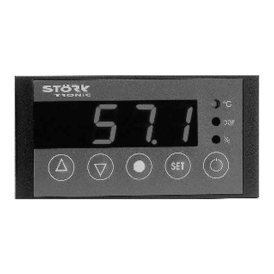
ST710-PWHVM.26
Six-stage controller
Order number 900205.004
Old Id.Nr.: 175539
Wiring diagram
Product description
The six-stage controller was developed for the control of compressor groups of up to 6 machines,
and/or the control of compressors with bypass-valves (max. 3 machines). The basic gas charac-
teristics are part of the fixed program data - therefore, it is possible to execute a pressure control
(4...20mA) and to show the temperature values at the same time. The compressor running times
can be optimised by help of the sequential or time-conditioned load replacement. The controller
that can be parametered in various ways has an alarm contact and a hour meter.
Front size: 84mm x 42mm
Panel cut-out: 67.5mm x 31.5mm
Connector: plug and socket
Advertisement

Related Manuals for Störk-Tronic ST710-PWHVM.26


Summary of Contents for Störk-Tronic ST710-PWHVM.26
- Page 1 ST710-PWHVM.26 Six-stage controller Order number 900205.004 Old Id.Nr.: 175539 Wiring diagram Product description The six-stage controller was developed for the control of compressor groups of up to 6 machines, and/or the control of compressors with bypass-valves (max. 3 machines). The basic gas charac- teristics are part of the fixed program data - therefore, it is possible to execute a pressure control...
- Page 3 SOFTWARE .26 Adjustment options Key UP Pressing this key you can increase the parameter or parameter value or scroll the parameter list. Key DOWN Pressing this key you can decrease the parameter or parameter value or scroll the parameter list. At alarm the buzzer function can be switched off with this key. Key Display: Shortly pressing this key shows the other value (“°C”, “bar”) of the actual display for 3 seconds.
- Page 4 First control level: After switching-on the mains voltage the display shows “OFF” if standby mode is activated and the actual value if the controller is not in standby mode. The LEDs have the following functions: “°C” = temperature display in °C (upper LED) “bar”...
- Page 5 Second control level (P parameters): Setting of control parameters Simultaneously pressing the UP and DOWN key for at least 4 seconds opens a parameter list containing control parameters. With the UP and DOWN keys the list can be scrolled in both directions. Pressing the SET key will give you the value of the respective parameter.
- Page 6 Para- Function description Adjustment range Standard Custom meter setting setting Total operating time contact K1 0 ... 25 years 0 years in years Total operating time contact K1 0 ... 364 days 0 days in days Total operating time contact K2 0 ...
- Page 7 Parameter description: P1: Setpoint 2 / Delta W1 P2: Setpoint 3 / Delta W2 P3: Setpoint 4 / Delta W3 P4: Setpoint 5 / Delta W4 P5: Setpoint 6 / Delta W5 Adjustment of the secondary setpoints. The respective secondary setpoint can be adjusted by parameters A10-A14 to be relative, i.e.
- Page 8 The operating time recorded by parameters P33-P44 is mainly used in the field of refrigeration technology to register the operating time of the connected compressors. P33: Total operating time contact K1 in years P35: Total operating time contact K2 in years P37: Total operating time contact K3 in years P39: Total operating time contact K4 in years P41: Total operating time contact K4 in years...
- Page 9 Third control level, (A parameters): Setting of control parameters Access to the third control level is granted when selecting the last P-parameter on the second control level. Continue to press the UP key for approximately 10 seconds until “PA” appears. Continue to press the UP key and additionally press the DOWN key for about 4 seconds and the first A-parameter of the third control level is indicated.
- Page 10 Para- Function description Adjustment range Standard Custom meter setting setting Minimum action time K3 “Off” 0...999 sec. 0 sec. Minimum action time K4 “Off” 0...999 sec. 0 sec. Minimum action time K5 “Off” 0...999 sec. 0 sec. Minimum action time K6 “Off” 0...999 sec.
- Page 11 Para- Function description Adjustment range Standard Custom meter setting setting Operating mode 0: K1-K6 without load replacement 1: K1+K2 with load replacement 2: K1+K2 as bypass-group (K1 = compressor) 3: K1-K3 with load replacement 4: K1-K4 with load replacement 5: K1-K4 as bypass-groups with load replacement (K1+K3 = compressor) 6: K1-K5 with load replacement...
- Page 12 Parameter description: The following values can change the equipment characteristics and are therefore to be set with utmost care. A1-A6: Function of contact K1-K6 at sensor error In case of sensor error (open or short circuit) the display shows “F1-“ flashing. At sensor error the respective relay falls back into the condition pre-set here.
- Page 13 here. This suppression does not apply to sensor error alarm or, if activated, external alarms. If range alarm is selected, this parameter is ineffective. A33: Operating time before time depending load replacement Load replacement depending on time is mainly used in the field of refrigeration technology to balance the use of the connected compressors.
- Page 14 A43: Adjustment of setpoint S1‘ (not available on all types of controllers) By closing switching input E1, setpoint S1 can be switched to a setpoint S1’. Setpoint S1’ can be either relative to setpoint S1 or an independent, freely adjustable, control setting. The setpoint S1’ can only be accessed if input E1 is closed.
- Page 15 Table of operation modes and power stages A44 = 0 17 % K1+K2 33 % K1+K2+K3 50 % K1+K2+K3+K4 67 % K1+K2+K3+K4+K5 83 % K1+K2+K3+K4+K5+K6 100 % A44 = 1 50 % K1+K2 100 % A44 = 2 K1+K2 50 % 100 % (K2 = bypass) A44 = 3...
- Page 16 A44 = 9 50 % K1+K2 100 % (K2 = inverted bypass) A44 = 10 25 % K1+K2 or K1+K3 50 % K1+K2+K3 75 % K1+K2+K3+K4 100 % (K2, K4 = invert. Bypass) A44 = 11 17 % K1+K2 or K1+K3 33 % K1+K2+K3 or K1+K3+K5 50 %...
- Page 17 Operation with different measuring and indicated value General notes Parameters A15 and A35 permit the independent selection of measured and indicated value. There are the possibilities temperature measuring with temperature display, temperature measuring with pressure display, pressure measuring with pressure display and pressure measuring with temperature display.
- Page 18 Partially reset EEPROM to temperature operation: Setpoints 1 und 1’ S1 = 0.0°C S1’ absolute = 0.0°C S1’ relative = 0.0 K A59 = 0.0 K Setpoints 2 to 6 P1 absolute = 10.0°C P1 relative = 10.0 K P2 absolute = 20.0°C P2 relative = 20.0 K P3 absolute = 30.0°C P3 relative = 30.0 K...
- Page 19 Partially reset EEPROM to pressure operation: for refrigerant R134A (A37 = 0) for refrigerant R22 (A37 = 1) Setpoints 1 and 1’ Setpoints 1 and 1’ S1 = 2.0 bar (or 0.7°C) S1 = 4.1 bar (or 0.5°C) S1' absolute = 2.0 bar S2 absolute = 4.1 bar S1' relative = 0.0 bar S2 relative = 0.0 bar...
- Page 20 For refrigerant R407C (A37 = 2) For refrigerant R404A (A37 = 3) Setpoints 1 and 1’ Setpoints 1 and 1’ S1 = 3.6 bar (or -0.1°C) S1 = 5.0 bar (or 0.0°C) S2 absolute = 3.6 bar S2 absolute = 5.0 bar S2 relative = 0.0 bar S2 relative = 0.0 bar A59 = 0.0 K...
- Page 21 LON-bus and serial communication General note The control program has some standardized variables of type “SNVT” which permit the communication with external units via LON-bus. There are input and output values. The input values permit settings for the controller, which are directly available for the control process. The output values indicate measuring values and status information of the unit.
- Page 22 Connection information Simultaneously pressing the keys SET, UP and DOWN sends a „Service-Pin“ message (the program version of the software is indicated in the display. The controller responds to a “wave” command with a display flashing 3 times. Note that if a data logger is used the node number will change at connection (the domain must remain “0”.
- Page 23 Connection to data logger General note The following listed measuring values as well as the inputs and outputs are available for the data logger TRL1 via LON interface. In general the setpoints and parameters all are accessible. Data logger protocol Parameter values (read/write) Adjustable parameters P1,P2,P3,P4,P5,P11,P12,P13,P14,P15,P16,P17,P18,P19,P21,...
- Page 24 Status messages Message Cause Error elimination Sensor error, short circuit Check sensor Sensor error, open circuit Check sensor Exceeding operating range Stick to operating range -is interpreted as error if measuring value (P35) and indicated value (P15) are different Flashing display Temperature alarm Data loss at parameter memory If error cannot be eliminated by (Contacts K1 and K2 are switched...
- Page 25 Technical data of ST710-PWHVM.26 Input External potential-free switching contact Measuring input Resistance thermometer Pt100 3-wire Measuring range: -200°C...350°C Measuring accuracy: 0.5K +/- 0.5 % of scale range, without sensor linear current input, 4...20mA, 2-wire connection Outputs Relay, normally-open contact, 6A 250V...
Need help?
Do you have a question about the ST710-PWHVM.26 and is the answer not in the manual?
Questions and answers