Table of Contents
Advertisement
Quick Links
Advertisement
Table of Contents

Subscribe to Our Youtube Channel
Related Manuals for F5 2000 Series

Summary of Contents for F5 2000 Series
- Page 1 Setting Up the 2000/4000 Series Platform MAN-0400-01...
-
Page 3: Table Of Contents
Table of Contents Table of Contents Legal Notices.............................5 Chapter 1: About the 2000/4000 Series Platform..........7 About the 2000/4000 Series platform..................8 Components provided with the platform...................8 Peripheral hardware requirements...................9 Chapter 2: Platform Installation................11 About general recommendations for rack mounting...............12 Unpacking the platform......................12 Determining which rack mounting kit to use................13 About the front-mounting kit....................13 Front-mounting kit hardware..................13... - Page 4 Table of Contents...
-
Page 5: Legal Notices
2012, F5 Networks, Inc. All rights reserved. F5 Networks, Inc. (F5) believes the information it furnishes to be accurate and reliable. However, F5 assumes no responsibility for the use of this information, nor any infringement of patents or other rights of third parties which may result from its use. - Page 6 Legal Notices RF Interference Warning This is a Class A product. In a domestic environment this product may cause radio interference, in which case the user may be required to take adequate measures. FCC Compliance This equipment has been tested and found to comply with the limits for a Class A digital device pursuant to Part 15 of FCC rules.
-
Page 7: Chapter 1: About The 2000/4000 Series Platform
Chapter About the 2000/4000 Series Platform ® Topics: The BIG-IP 2000/4000 Series platform is a powerful system that is capable of managing traffic for any size of enterprise. • About the 2000/4000 Series platform • Components provided with the platform •... -
Page 8: About The 2000/4000 Series Platform
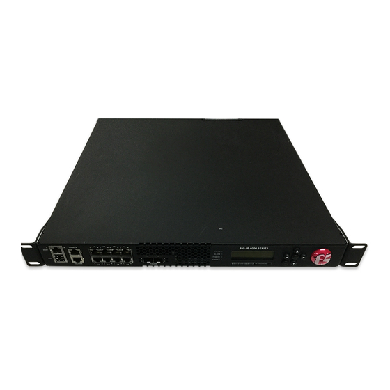
About the 2000/4000 Series Platform About the 2000/4000 Series platform Before you install the 2000/4000 Series platform, review helpful information about the controls and ports located on both the front and the back of the platform. On the front of the platform, you can reset the unit using the LCD panel. You can also use the front-panel LEDs to assess the condition of the unit. -
Page 9: Peripheral Hardware Requirements
Setting Up the 2000/4000 Series Platform Quantity Hardware RJ45 to RJ45 failover cable, CAT 5 crossover (blue) RJ45 to DB9 console port cable (beige) RJ45F to RJ45M rolled adapter (beige) Front-mounting kit Quick-install rail kit Peripheral hardware requirements For each platform, you might need to provide additional peripheral hardware. If you plan to remotely administer the system, it would be helpful to have a workstation already connected to the same subnet as the management interface. - Page 10 About the 2000/4000 Series Platform...
-
Page 11: Chapter 2: Platform Installation
Chapter Platform Installation Topics: After you have reviewed the hardware requirements and become familiar with the 2000/4000 Series platform, you can install the • About general recommendations for rack unit. mounting • Unpacking the platform • Determining which rack mounting kit to use •... -
Page 12: About General Recommendations For Rack Mounting
Caution: To ensure your safety and to prevent damage to the platform, F5 Networks recommends that at least two people remove the platform from the shipping box. -
Page 13: Determining Which Rack Mounting Kit To Use
Setting Up the 2000/4000 Series Platform 3. Remove the platform from the box and remove the foam inserts. 4. Remove the platform from the plastic bag. 5. Place the platform on a flat surface until you are ready to install the platform into a rack. Determining which rack mounting kit to use The 2000/4000 Series platform comes with two types of rack mounting kits: stationary front-mounting and sliding quick-install rail-mounting. -
Page 14: About The Quick-Install Rail Kit
The unit must be securely fastened to the rack to provide adequate stability and to prevent the unit from falling out of the rack. If the rack you have does not provide adequate support for the unit, you might need a shelf kit. F5 Networks recommends using a shelf kit created by the rack manufacturer, if available. -
Page 15: Installing The Rail Lock Brackets
Setting Up the 2000/4000 Series Platform Installing the rail lock brackets The rail lock brackets help secure a quick-install rail kit-mounted platform to a rack. 1. Attach the rail lock brackets to each side of the unit using the rail lock screws that are included in the kit. -
Page 16: Connecting The Cables And Other Hardware
1. Connect the system to a management workstation or network. • If you are using a serial terminal as the console, connect the serial console cable supplied by F5 Networks to the CONSOLE port. Important: In the event that network access is impaired or not yet configured, the serial console might be the only way to access the unit. -
Page 17: Configuring A Management Ip Address Using The Lcd Panel
Setting Up the 2000/4000 Series Platform Configuring a management IP address using the LCD panel You can use the LCD panel to configure the management IP address. The management IP address enables you to access the Configuration utility to configure other aspects of the product, such as the product license, VLANs, and trunks. - Page 18 Platform Installation...
-
Page 19: Appendix A: Environmental Guidelines
Appendix Environmental Guidelines Topics: • General environmental guidelines • Guidelines for AC-powered equipment • Guidelines for DC-powered equipment... -
Page 20: General Environmental Guidelines
Do not plug the unit into a branch circuit shared by more electronic equipment than the circuit is designed to manage safely at one time. Important: This product is sensitive to electrostatic discharge (ESD). F5 Networks recommends that you use proper ESD grounding procedures and equipment when you install or maintain the unit. -
Page 21: Guidelines For Ac-Powered Equipment
Setting Up the 2000/4000 Series Platform Guidelines for AC-powered equipment An AC-powered installation must meet these requirements: • Use a 15 amp external branch circuit protection device to install the unit. • Use one power feed for each individual power supply. Caution: Customers should not attempt to replace batteries. -
Page 22: Guidelines For Dc-Powered Equipment
Environmental Guidelines Guidelines for DC-powered equipment A DC-powered installation must meet these requirements: • Use a 15 amp external branch circuit protection device to install the unit. • For permanently connected equipment, incorporate a readily accessible disconnect in the fixed wiring. •... -
Page 23: Appendix B: Repackaging Guidelines
Appendix Repackaging Guidelines Topics: If it becomes necessary to transport the platform to another location or return it to F5 Networks, these guidelines will help ensure that • Repackaging the platform you repackage the platform properly. Important: Before returning any equipment, contact F5 Networks to obtain a Return Material Authorization (RMA) case number. -
Page 24: Repackaging The Platform
Repackaging Guidelines Repackaging the platform The 2000/4000 Series platform must be shipped in packaging provided by F5 Networks. 1. Disconnect the network cables and other cables from the platform, and then remove any optical modules. 2. Remove the platform from the rack. - Page 25 Setting Up the 2000/4000 Series Platform 7. Close and seal the shipping box.
- Page 26 Repackaging Guidelines...
- Page 27 Index Index AC-powered equipment guidelines 21 management interface 16 management IP address configuring using LCD panel 17 cables connecting 16 CD/DVD-ROM drives NEBS support for 9 air temperature 20 chassis ground location of 8 pass-through adapter, See RJ45F to RJ45M rolled serial adapter. platform DC-powered equipment about 8...
- Page 28 Index serial failover 16 unpacking serial terminal platform 12 hardware installation, and 9, 16 USB port switches 9 supported CD/DVD-ROM drives 9 USB thumb drives support for 9 transporting the platform 23 two-post rack 13 warnings environmental 20...
Need help?
Do you have a question about the 2000 Series and is the answer not in the manual?
Questions and answers