Advertisement
Quick Links
SHOE
Pleas
Note: B
Before
surfa
TH
HIS INSTRU
UCTION BO
PL
LEASE REA
AD AND KEE
Wh
halen Storag
ge
MANHA
ATTAN
E SHELF
F 40"Hx2
As
ssemb
HDC #
#:91558
MFG #
#:WSH
se read
d over t
tim
me-save
Assem
mbly, ple
ace to
avoid a
OKLET CO
NTAINS IM
EP FOR FUT
TURE REFE
MODUL
LAR STO
21"Wx1
7"D CH
ly Inst
tructio
800120
0/91558
CSSU&
&WSHW
he instr
ructions
er in the
e long r
ease be
e sure t
any dam
mage to
MPORTANT
T SAFETY I
ERENCE.
Factory No.:
F
15548
ORAGE
E
ERRY/W
WHITE
ons
800410
WSSU
s; it will
l be a
un.
to work
k on a s
o the fin
nish.
INFORMAT
TION.
Page #1
soft flat
of 11
Advertisement

Related Manuals for Home Decorators Collection Manhattan WSHCSSU


Summary of Contents for Home Decorators Collection Manhattan WSHCSSU
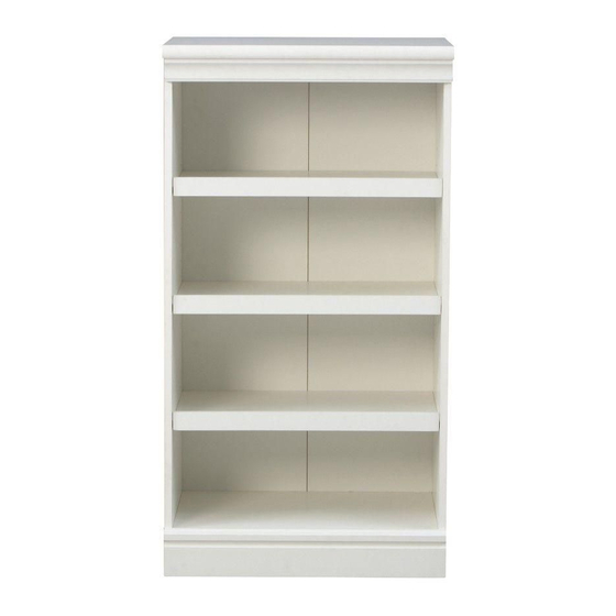
- Page 1 MANHA ATTAN MODUL LAR STO ORAGE SHOE E SHELF F 40"Hx2 21"Wx1 7"D CH ERRY/W WHITE ssemb ly Inst tructio HDC # #:91558 800120 0/91558 800410 MFG # #:WSH CSSU& &WSHW WSSU Pleas se read d over t he instr ructions s;...
-
Page 2: Assembly Tips
M A X I M U M R E C O M M E N D E D W E I G H T L O A D S MAXIMUM LOAD: 30 LBS. (13.6KG) This unit is intended for use only with the maximum weights indicated. - Page 3 Important Before you begin: Open, identify and count all parts prior to assembly. Lay out parts on a flat and non-abrasive surface. You will need the parts identified on page 3 and 4 of this instruction manual. NOTE: IT IS VERY IMPORTANT TO USE GLUE WITH DOWELS. EXCESS GLUE CAN BE WIPED OFF WITH DAMP CLOTH.
-
Page 4: Parts List
Parts List Please read completely through the instructions and verify that all parts listed are present before beginning assembly. 1-Top Panel (x 1) 2- Upper Front Molding (x 1) 3- Stretcher (x 1) 4-Side Panel Left (x 1) 5- Side Panel Right (x 1) 6- Adjustable Shelf (x 3) 7- Bottom Panel (x 1) 8- Back Panel (x 1) - Page 5 ardware L List ease read c completely y through th he instructi ions and ve erify that a all hardwar re listed are e present efore begin nning assem mbly. A-Cam Lock ( (x 21) B- C Cam Bolt (x 2 - M8x30 mm m Dowel (x 2 Plastic Conn...
- Page 6 Assembly Instructions 1. Connect Lower Front Molding (9) to Bottom Panel (7) by attaching 2 Plastic Connectors (D) at the joint with M3.5x12 mm Pan Head Screw (E), using the pilot holes as a reference. Tighten the Screws with the Phillips Screwdriver.
- Page 7 Assembly Instructions 4. Secure Lower Front Molding (9) to the Side Panels (4 & 5) by attaching 2 Plastic Connectors (D) at the joints with the M3.5x12 mm Pan Head Screws (E) into the pilot holes. 5. Gently tap the Floor Protectors (L) at the bottom of side panels avoiding crack or damage of side panel. Attach Upper Front Molding (2) to Top Panel (1) by using two M8x30 mm Dowel (C) and 2 Plastic Connectors (D).
- Page 8 Assembly Instructions Insert the M8x30mm Dowels (C) into the middle holes as a guide, attach the Top Panel (1) to assembled frame by engaging 6 Cam Locks (A) as shown below. 9. Expand the Back Panel (8) and lay it onto the back edges of assembled frame making sure the margins along all edges are equal.
- Page 9 Assembly Instructions 10. Screw 3 Cam Bolts (B) all the way into the small holes located on Adjustable Shelf Front Molding (10). Insert the M8x30mm Dowels (C) into the middle holes as a guide, attach the Adjustable Shelf Front Molding (10) to Adjustable Shelf (6) by engaging 3 Cam Locks (A) as shown below.
-
Page 10: Tipping Restraint Hardware
Assembly Instructions NOTE: If you buy more than one unit, the stacking configuration can be available. 14. This cabinet featured stacking configuration. Repeat the same procedure to assemble the other shoe shelf unit. Place one unit on the top of the other base unit making sure it is centered properly and back edges are even. Using the Metal Bracket (J) as a template, mark the mounting hole locations at the back side of the Base Top Panel and Hutch Side Panels, as shown in the illustration. -
Page 11: Care And Maintenance
Care and Maintenance Use a soft, clean cloth that will not scratch the surface when dusting. Use of furniture polishes is not necessary. Should you choose to use polishes, test in an inconspicuous area first. Using solvents of any kind on your furniture may damage the finish. ...
Need help?
Do you have a question about the Manhattan WSHCSSU and is the answer not in the manual?
Questions and answers