Table of Contents
Advertisement
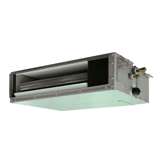
ARUM24TLAV2
ARUM30TLAV2
ARUM36TLAV2
INSTALLATION MANUAL
For authorized service personnel only.
MANUEL D'INSTALLATION
UNITÉ INTÉRIEURE (type conduit)
Pour le personnel agréé uniquement.
MANUAL DE INSTALACIÓN
UNIDAD INTERIOR (Tipo conducto)
Únicamente para personal de servicio autorizado.
PART No. 9373385264-02
INDOOR UNIT (Duct type)
Advertisement
Table of Contents

Subscribe to Our Youtube Channel
Related Manuals for Fujitsu Airstage ARUM24TLAV2


Summary of Contents for Fujitsu Airstage ARUM24TLAV2
- Page 1 INSTALLATION MANUAL INDOOR UNIT (Duct type) For authorized service personnel only. MANUEL D’INSTALLATION UNITÉ INTÉRIEURE (type conduit) Pour le personnel agréé uniquement. MANUAL DE INSTALACIÓN UNIDAD INTERIOR (Tipo conducto) Únicamente para personal de servicio autorizado. ARUM24TLAV2 ARUM30TLAV2 ARUM36TLAV2 PART No. 9373385264-02...
-
Page 2: Table Of Contents
INSTALLATION MANUAL 1.2. SPECIAL PRECAUTIONS PART No. 9373385264-02 When Wiring VRF system indoor unit (Duct type) ELECTRICAL SHOCK CAN CAUSE SEVERE PERSONAL INJURY OR DEATH. ONLY A QUALIFIED, EXPERIENCED ELECTRICIAN SHOULD ATTEMPT TO WIRE THIS Contents SYSTEM. • Do not supply power to the unit until all wiring and tubing are completed or reconnected 1. -
Page 3: About This Product
2. ABOUT THIS PRODUCT Special nut A For suspending the indoor unit (large flange) from ceiling 2.1. Precautions for using the R410A refrigerant Special nut B WARNING (small flange) Do not introduce any substance other than the prescribed refrigerant into the refrigera- tion cycle. -
Page 4: About Unit Of The Length
Other optional parts 3.2. Installation dimensions Description Model Application Provide the space around the unit as Unit: in (mm) IR receiver unit UTY-TRHX For the wireless remote controller. shown in the following figure. Drain pump unit UTZ-PU1NBA *1: 16 in (400 mm) or more when drain from drain pipe. - Page 5 3.3.4. Outlet duct WARNING Duct installation pattern ( CUT PART) When fastening the hangers, make the bolt positions uniform. Round duct outlet 4 (Factory setting.) Square duct The distance of is adjustable according to the place of the hanging bolts. (MAX.: 21-5/8 in (550 mm), MIN.: 16-1/8 in (410 mm)) Slide the unit in the arrow direction and fasten it.
-
Page 6: Pipe Installation
3.3.5. Fresh air intake 4.2. Pipe requirement (Processing before use) (1) When taking in fresh air, cut a slit CAUTION shaped cabinet in the left side of the outer case with nippers. Refer to the Installation Manual of the outdoor unit for description of the length of con- necting pipe or for difference of its elevation. -
Page 7: Installing Heat Insulation
4.3.3. Pipe connection (Left side) Unit: in (mm) 9-7/16 (240) CAUTION Be sure to install the pipe against the port on the indoor unit correctly. If the centering is improper, the flare nut cannot tighten smoothly. If the flare nut is forced to turn, the threads will be damaged. -
Page 8: Electrical Wiring
Hose opening view WARNING Wind the attached heat insulation If the supply cable is damaged, it must be replaced by the manufacturer, its service around the hose band. Make sure the agent or similarly qualified persons in order to avoid a hazard. alignment is on top. -
Page 9: Wiring Method
B. For strand wiring 6.2. Wiring method (1) Use ring terminals with insulating sleeves as shown in the figure below to connect to EXAMPLE the terminal block. (2) Securely clamp the ring terminals to the cables using an appropriate tool so that the Outdoor unit or RB unit *1 cables do not come loose. -
Page 10: Connection Of Wiring
6.4. Connection of wiring 6.5. Optional parts wiring 6.5.1. Layout of the indoor unit PCB (1) Remove the control box cover and install each connection cable. Power supply PCB Controller PCB CNB01 CNA01 CNA03 CNA02 CNA04 CN48 CNA05 Power indicator lamp (green) Control box cover Screw... -
Page 11: External Input And External Output (Optional Parts)
Wiring arrangement When connected to Apply voltage terminals of multiple indoor units with a connected unit, be sure to make a branch outside the indoor unit using a pull box, etc. as shown on below In following figure, all the possible connectors are connected for description. example. -
Page 12: Remote Sensor (Optional Parts)
Operation behavior Operation behavior ● Input signal type * If function setting "60" is set to "00" Edge The input signal type can be selected. Connector Output voltage Status It is switched by DIP switch on the indoor unit PCB. Stop External output 1 DIP switch [SET2 SW2]... -
Page 13: Field Setting
7. FIELD SETTING 7.2. Custom code setting Selecting the custom code prevents the indoor unit mix-up. There are 3 methods for address setting by FIELD SETTING as follows. (Up to 4 codes can be set.) Set by either of the methods. Perform the setting for both the indoor unit and the remote controller. -
Page 14: Function Setting
Function 7.4. Function setting Details Function Setting number Default number Auxiliary • FUNCTION SETTING can be performed with the wired or wireless remote controller. heater con- (The remote controller is optional equipment) trol 1 • Refer to the wired or wireless remote controller manual for detailed setting information. Auxiliary •... -
Page 15: Test Run
Function 8. TEST RUN Details Function Setting number Default number 00 Disable Standby 8.1. Test run using Outdoor unit (PCB) 01 1 minutes Sets the standby time until the time for 02 2 minutes auxiliary equipment operation auxiliary starts during primary equipment •... -
Page 16: Error Codes
10. ERROR CODES If you use a wired type remote controller, error codes will appear on the remote controller display. If you use a wireless remote controller, the lamp on the photodetector unit will output error codes by way of blinking patterns. See the lamp blinking patterns and error codes in the table below.
Need help?
Do you have a question about the Airstage ARUM24TLAV2 and is the answer not in the manual?
Questions and answers