Table of Contents
Advertisement
Available languages
Available languages
Quick Links
T-FAST MINI
Modulo di produzione ACS
DHW production modules
Frischwasserstationen
Modules de production ECS
Istruzioni per l'installazione, l'uso e la manutenzione
Assembling instructions and maintenance
Montage - und Wartungsanleitung
Instructions relatives à l'installation, l'utilisation et la maintenance
Advertisement
Table of Contents

Subscribe to Our Youtube Channel
Related Manuals for Lovato T-FAST MINI


Summary of Contents for Lovato T-FAST MINI
- Page 1 T-FAST MINI Modulo di produzione ACS DHW production modules Frischwasserstationen Modules de production ECS Istruzioni per l’installazione, l’uso e la manutenzione Assembling instructions and maintenance Montage - und Wartungsanleitung Instructions relatives à l’installation, l’utilisation et la maintenance...
- Page 2 SEZIONE 9: COMPONENTI E ACCESSORI Illustrazioni e dati presenti si intendono non impegnativi. LOVATO Spa si riserva il diritto di apportare modifiche senza obbligo di preavviso. È vietata la riproduzione parziale o totale di disegni, testi o illustrazioni senza autorizzazione scritta.
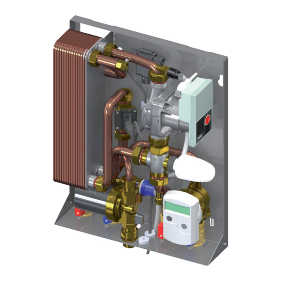
- Page 3 DESCRIZIONE T-FAST MINI è un modulo di produzione istantanea di acqua calda sanitaria che utilizza uno scambiatore a piastre saldobrasate in acciaio inox, la regolazione della temperatura dell’acqua calda sanitaria avviene attraverso la miscelazione termostatica del fluido del circuito primario.
- Page 4 Installazione, uso e manutenzione SEZIONE 2: DATI TECNICI COMPONENTI PRINCIPALI Contabilizzatore di energia ad ultrasuoni 1,5 mc/h CL2 (accessorio), standard dima d’attesa 110 x G ¾” Valvola a sfera DN 20 M - F ¾" Circolatore Wilo YONOS PARA 15/1-6 130 Valvola a 3 vie DN20 - M-M-M G 1”...
- Page 5 Idrogeno Carbonato/Solforato mg/l >1.0 Solfuro mg/l <1 I materiali di costruzione del modulo di produzione acqua calda sanitaria mod. T-FAST MINI sono conformi a quanto previsto dal D.M. 174/2004, regolamentato Nitrato mg/l <100 dalla Direttiva 98/83/CE. Nitrito mg/l <0.1...
- Page 6 Installazione, uso e manutenzione SEZIONE 4: ESEMPI DI UTILIZZO M-BUS VAnO ScALe UNITà ABITATIVA CENTRALE TERMICA MANDATA RITORNO ACQUA FREDDA SANITARIA ACQUA CALDA SANITARIA SEZIONE 5: INSTALLAZIONE CONTROLLI PRELIMINARI Prima di ogni operazione rimuovere con cura l’imballo e controllare la perfetta integrità dell’apparecchiatura. Nel caso si evidenziassero dei difetti o dei danni non installare o cercare di riparare l’apparecchiatura ma rivolgersi al venditore.
- Page 7 Installazione, uso e manutenzione INSTALLAZIONE PENSILE ATTenZIOne! MANEGGIARE CON CURA! Estrarre con cura il modulo dall’imballaggio facendo attenzione a non danneggiarlo e rimuo- vere il coperchio. n.B. TASSELLI ESCLUSI DALLA IMPORTANTE! FORNITURA POSIZIONARE IL MODULO IN MANIERA CORRETTA 2a 2a Fissare a muro n.3 tasselli da 12 mm (fig.2), rispettando le distanze come da rif.
- Page 8 Installazione, uso e manutenzione ES.1: INSTALLAZIONE PENSILE ES.2: INSTALLAZIONE AD INCASSO SEZIONE 6. MESSA IN FUNZIONE 1 - Aprire le valvole a sfera (A e B), riempire il circuito primario e sfiatare l’aria presente. 2 - Riempire il circuito secondario (sanitario) . 3 - Controllare la tenuta idraulica del modulo e sfiatare l’aria presente per un buon rendimento dell’impianto.
- Page 9 Installazione, uso e manutenzione INSTALLAZIONE E MESSA IN FUNZIONE KIT DI RICIRCOLO 1,00 0,90 Lowara/Xylem EB 15-1/94 R 0,80 0,70 0,60 Rubinetto di intercettazione 0,50 0,40 Valvola di 0,30 ritegno DP kit ricircolo 0,20 Q (l/h) PERICOLO! APPARECChIO IN TENSIONE - Intercettare il flusso chiudendo le valvola a sfera “ingresso AFS”...
- Page 10 Installazione, uso e manutenzione SEZIONE 7. REGOLAZIONI SCHEMA COLLEGAMENTO ELETTRICO POMPA-FLUSSOSTATO ATTUATORE TERMOSTATICO: REGOLAZIONE TEMPERATURA USCITA ACS (Fig. D) (Fig. E) pos. t (°C) REGOLAZIONE DI FABBRICA (Figura D) FERMO TESTA (Figura E) SCHEMA COLLEGAMENTO ELETTRICO POMPA-FLUSSOSTATO 8. COLLEGAMENTO ELETTRICO POMPA / FLUSSOSTATO FLUX 230 V FLUX...
- Page 11 Installazione, uso e manutenzione SEZIONE 8: COMPONENTI E ACCESSORI VALVOLA 3 VIE MISCELATRICE Funzione: regolazione della temperatura acqua calda sanitaria. La valvola a 3 vie può essere regolata mediante: - attuatore termostatico impostabile da 40 a 70°C (fig.3) avente bulbo in mandata secondario. Il funzionamento della testina è a dilatazione di liquido contenuto nella stessa.
- Page 12 Installazione, uso e manutenzione CIRCOLATORE AD ALTA EFFICIENZA CIRCUITO PRIMARIO Circolatore ad alta efficienza circuito primario Wilo YONOS PARA 15/1-6 Connessione elettrica: - 3 cavi di alimentazione 230V/ 50Hz AC Alimentazione: nero/marrone: L1, 230V/AC 50-60Hz Blu: N, neutro Giallo/verde: terra N.B.
- Page 13 SECTION 8: PUMP / FLOW SWITCH ELECTRICAL CONNECTION SECTION 9: COMPONENTS Picture and technical data are not binding. LOVATO Spa will reserve the right to bring change without obbligation of notice. It is forbidden reproduce copy, drawing or texties, partial or total without previous written authorization.
- Page 14 DESCRIPTION T-FAST MINI is a DHW production module that uses the working principle of a stainless steel plate heat exchanger. The temperature of the water is managed by a thermostatic mixing valve on the primary circuit. The pump, placed on the primary circuit is activated to the signal of the flowswitch that is placed on the secondary circuit. For optimized the comfort a secondary return kit is available.
- Page 15 Assembling instructions and maintenance SECTION 2: TEChNICAL DATA COMPONENTS Ultrasonic heat meter 1,5 mc/h CL2 (separately supplied), fitting piece for heat meter standard 110 x G ¾” DN 20 ball valve - connection M - F ¾" High efficiency pump type Wilo Yonos Para 15/1-6 DN20 3-port mixing valve - connection M-M-M G 1”...
- Page 16 Assembling instructions and maintenance HYDRAULIC CIRCUIT 1 Heat meter 2 Ball valve 3 Pump 4 Thermostatic valve 5 Heat exchanger 6 Safety valve 7 Sensor pocket for thermostatic valve 8 Check valve 10 Bar 9 Circulation valve 10 Flow switch SECTION 3: DIMENSIONS AND CONNECTIONS DHW outlet Primary return...
- Page 17 Assembling instructions and maintenance SECTION 4: EXAMPLE OF APPLICATION M-BUS DWELLING BOILER ROOM Max ∆P 30 KPa SUPPLY RETURN DOMESTIC COLD WATER DOMESTIC HOT WATER SECTION 5: INSTALLATION PRELIMINARy ChECK Before every operation carefully remove the packaging and verify if there is external damages. In case of damages please do not install the products. Dispose the packaging parts in compliance with the local regulations.
- Page 18 Assembling instructions and maintenance WALL HUNG INSTALLATION ATTenTIOn! HANDLE IT WITH CARE! Pull out the module from the package and remove the cover. SCREW ANCHORS NOT IMPORTANT! SUPPLIED PLACE THE BRACKET IN THE CORRECT PLACE 2a 2a Fix No. 3 plugs on the wall (picture 2) respecting the distance as shown in rif.
- Page 19 Assembling instructions and maintenance ES.1: WALL HUNG INSTALLATION ES.2: BUILT-IN INSTALLATION SEZIONE 6: MODULE START UP 1 - Open the ball valves (A e B), Fill the primary circuit and venting the air 2 - Fill the secondary circuit (domestic hot water) . 3 - Check the hydraulic tight.
- Page 20 Assembling instructions and maintenance RECIRCULATION KIT CONNECTIONS AND START UP 1,00 0,90 Lowara/Xylem EB 15-1/94 R 0,80 0,70 0,60 Ball valve 0,50 0,40 Check 0,30 valve DP kit ricircolo 0,20 Q (l/h) DANGER! POWERED DEVICE - Shut-off the flow closing the ball valves “DCW supply” ref. 1 and “DHW outlet”...
- Page 21 Assembling instructions and maintenance SECTION 7: SETTINGS SCHEMA COLLEGAMENTO ELETTRICO POMPA-FLUSSOSTATO THERMOSTATIC ACTUATOR: DHW TEMPERATURE SETTING (Fig. D) (Fig. E) pos. t (°C) PRE-SET FACTORy REGULATION (Fig. D) NO-BURNING PROTECTION (Fig. E) SCHEMA COLLEGAMENTO ELETTRICO POMPA-FLUSSOSTATO 8. PUMP / FLOW SWITCh ELECTRICAL CONNECTION FLUX 230 V FLUX...
- Page 22 Assembling instructions and maintenance SECTION 8: COMPONENTS 3-PORT MIXING VALVE Function: DHW temperature settings The mixing valve must be controlled by: - settable thermostatic actuator from 40 to 70°C with bulb (heating secondary flow). he expansion of the liquid inside the bulb determine the functioning of the valve.
- Page 23 Assembling instructions and maintenance PRIMARY CIRCUIT PUMP CHARACTERISTICS High efficiency pump type Wilo YONOS PARA 15/1-6 Electric connection: - 3 power wires 230V/ 50Hz AC Supply: Black/brown: L1, 230V/AC 50-60Hz Blue: N, neutral Yellow/green: protective ground Note: circulator data and values are available on the Wilo manual included in the packaging. ∆P VARIABLE ∆P CONSTANT...
- Page 24 ABSCHNITT 9: KOMPONENTE Abbildungen und technische Daten sind nicht bindend. Die LOVATO SpA behält sich das Recht vor Änderungen, ohne Ankündigungen oder Mitteilungen vorzunehmen. Es ist verboten Dokumente, Zeichnungen oder Texte, teilweise oder vollständig ohne vorherige schriftliche Genehmigung, durch die LOVATO SpA, zu kopieren.
- Page 25 Anlage übernehmen.. Die LOVATO SpA ist nicht für das Produkt verantwortlich, wenn unerlaubte Veränderungen vorgenommen wurden oder Originalkomponentendurch Fremdteile ersetzt wurden. Ohne schriftliche Genehmigung des Herstellers ist es nicht gestattet, Veränderungen, An- und Umbauten amGerät vorzunehmen. Es ist zudem nicht gestattet, Zusatzkomponenten einzubauen, welche nicht zusammen mit dem Gerät geprüft worden sind.
- Page 26 Montage - und Wartungsanleitung ABSChNITT 2: TEChNISChE DATEN BESTANDTEILE: Ultraschall-Energiemengenzähler 1,5 mc/h CL2 (separat geliefert), standard dima d’attesa 110 x G ¾” Kugelventil DN 20 M - F ¾" Pumpe Wilo YONOS PARA 15/1-6 3-Wege-Mischerventil DN20 - M-M-M G 1” Thermostatischem Antrieb 40 ÷...
- Page 27 <300 Anlage verringern kann. Hydrogencarbonat / mg/l >1.0 Die Herstellungsmaterialien der Module Typ T-FAST MINI entsprechen dem Dekret Schwefelwasserstoff D.M. 174/2004, sowie den Richtlinien 98/83/CE. Sulfid mg/l <1 Obwohl das System ab Werk vormontiert ist, wird empfohlen alle Schraubverbind-...
- Page 28 Montage - und Wartungsanleitung ABSChNITT 4: ANWENDUNGSBEISPIEL M-BUS WOhNUNGSEINhEIT hEIZUNGSZENTRALE Max ∆P 30 KPa EINLASS RÜCKLASS KALTWASSER WARMWASSER ABSChNITT 5: INSTALLATION VORPRÜFUNGEN Vor jeder Arbeit ist die Verpackung sorgfältig zu entfernen und der Gerätezustand zu überprüfen. Bei Feststellung von Fehlern oder Schäden nicht instal- lieren oder versuchen zu reparieren.
- Page 29 Montage - und Wartungsanleitung INSTALLATION AUFHäNGEVERSION AChTUNG! MIT SORGFALT BEHANDELN! Das Modul aus der Verpackung entnehmen und die Abdeckung entfernen. ANMERKUNG: DÜBEL IM LIEFE- WIChTIG! RUMFANG NICHT ENTHALTEN DIE HALTERUNG KORREKT POSIZIONIEREN 2a 2a Dübel zu 12 mm (Abb.2) an die Wand befestigen, Freiraum einhal- ten gemäß...
- Page 30 Montage - und Wartungsanleitung ES.1: INSTALLATION AUFHÄNGEVARIANTE ES.2: INSTALLATION UNTERPUTZVARIANTE ABSChNITT 6: INBETRIBNAhME DES MODULS 1 - Ventile aufmachen (A e B), Primärklreislauf einfüllen und Luft auslassen. 2 - Sekundärkreis einfülle (Sanitäranlage) . 3 - Modul hydraulisch testen und Luft auslassen, um eine korrekte Einfüllung der Anlage zu garantieren.
- Page 31 Montage - und Wartungsanleitung INSTALLATION UND INBETRIEBNAHME ZIRKULATIONSSET 1,00 0,90 Lowara/Xylem EB 15-1/94 R 0,80 0,70 0,60 Absperrventil 0,50 0,40 0,30 Rückschlagventil DP kit ricircolo 0,20 Q (l/h) hOChSPANNUNG! - Durchfluss durch Schließen des Kugelhahns “Eingabe Frischwasser” Ref. 1 und Ausgang “Warmwasser” Ref. 2 festhalten - Die Kappe ¾...
- Page 32 Montage - und Wartungsanleitung ABSChNITT 7 : REGULIERUNG SCHEMA COLLEGAMENTO ELETTRICO POMPA-FLUSSOSTATO THERMOSTAT ANTRIEB: REGULIERUNG DER WARMWASSERAUSLASSTEMPERATUR (Fig. D) (Fig. E) pos. t (°C) (Fig. D) Werkseitig eingestellter Wert (Figura E) Verbrühungsschutz SCHEMA COLLEGAMENTO ELETTRICO POMPA-FLUSSOSTATO ABSChNITT 8 : ELEKTRISChE VERBINDUNG DER PUMPE / FLUSSREGLER FLUX 230 V FLUX...
- Page 33 Montage - und Wartungsanleitung ABSChNITT 9: KOMPONENTE 3-WEGE MISCHERVENTIL Funktion: Temperatureinstellung Warmwasser Der Dreiwegeventil kann wie folgt eingestellt werden: - Absperrventil von 40 bis 70°C (Abb.3) mit Birne im Einlass Sekundärkreis. Der Thermostatkopf funktioniert nach dem Prinzip der Ausdehnung der Flüssigkeit. Anschluss M30x1,5. Temperatur 40 ÷ 55°C 3-Wege-Ventil aus Messing und mit 3 Gewindeanschlüsse, G 1”...
- Page 34 Montage - und Wartungsanleitung HOCHEFFIZIENZPUMPE IM PRIMäRKREIS Hocheffizienzpumpe im Primärkreis Wilo YONOS PARA 15/1-6 Elektrischer Anschluss: - 3 Stromkabel 230V / 50Hz AC Leistung: schwarz / braun: L1, 230V/AC 50-60Hz Blau: N, neutral Gelb / Grün: Erde Anmerkung: alle Daten der Pumpen sind in der Wilo-Betriebsanleitung in der Verpackung enthalten. ∆P VARIABEL ∆P KONSTANT Für weitere Informationen zu den Pumpen bitte das Wilo-Handbuch in der Verpackung nachsehen.
-
Page 35: Table Of Contents
SECTION 9: ACCESSOIRES Les illustrations et les données indiquées dans ce catalogne n’engagent pas la société. LOVATO SpA qui se réserve le droit d’apporter des modifications sans obligation de préavis. La reproduction partielle ou totale des plans, des textes ou des illustrations est interdite sans autorisation écrite. -
Page 36: Section 1: Introduction
La société LOVATO S.p.A. sauf autorisation ne s’assume aucune responsabilité en présence d’un produit modifié et ceci s’applique aussi lors de l’utilisation de pièces de rechange non originales. -
Page 37: Section 2: Donnèes Techniques
Instructions relatives à l’installation, l’utilisation et la maintenance SECTION 2: DONNÈES TEChNIqUES 2. Indications générales STRUCTURE: Comptabilisateur d’énergie thermique ultrasons 1,5 mc/h CL2 (livrés séparément), gabarit standard 110 x G ¾” Vanne à bille DN 20 M - F ¾" Pompe de circulation YONOS PARA 15/1-6 Vanne mélangeuse à... -
Page 38: Circuit Hydraulique
Hydrogène Carbonate / Sulfuré mg/l >1.0 Les matériaux de construction du module de production eau chaude sanitaire modèle T-FAST MINI respectent la réglementation objet de l’arrêté ministériel Sulfure mg/l <1 174/2004, et ce conformément à la Directive 98/83/CE. -
Page 39: Section 4: Exemple D'utilisation
Instructions relatives à l’installation, l’utilisation et la maintenance SECTION 4: EXEMPLES D’UTILISATION M-BUS hABITATION CAGE D’ESCALIER CENTRALE ThERMIqUE Max ∆P 30 KPa REFOULEMENT RETOUR EAU FROIDE SANITAIRE EAU CHAUDE SANITAIRE SECTION 5: INSTALLATION CONTROLES PRELIMINAIRES Avant toute opération, veuillez enlever délicatement l’emballage et contrôler l’intégrité parfaite de l’appareillage. Dans le cas où vous constateriez des défauts ou des dommages, veuillez-vous adresser au revendeur et surtout veuillez ne pas installer ou tenter de réparer l’appareillage. - Page 40 Instructions relatives à l’installation, l’utilisation et la maintenance ATTenTIOn ! MANIPULER EN FAISANT ATTENTION! Extraire de l’emballage le module et enlever le couvercle. n.B. LES CHEVILLES SONT IMPORTANT! EXCLUES DE LA FOURNITURE. POSITIONNER LE SUPPORT DE FACON CORRECTE 2a 2a Fixer sur le mur n.3 vis de 12 mm (fig.2) et respecter les distances com- me représenté...
-
Page 41: Section 6: Mise En Service
Instructions relatives à l’installation, l’utilisation et la maintenance ES.1: INSTALLATION MEUBLE SUSPENDU ES.2: INSTALLATION à ENCASTREMENT SECTION 6: MISE EN SERVICE 1 - Ouvrir les robinets à billes (A e B), remplir le circuit primaire et purger l’air 2 - Remplir le circuit secondaire (eau chaude sanitaire). 3 - Vérifier l’étanchéité... -
Page 42: Installation Et Mise En Service Kit De Recirculation
Instructions relatives à l’installation, l’utilisation et la maintenance INSTALLATION ET MISE EN SERVICE KIT DE RECIRCULATION 1,00 0,90 Lowara/Xylem EB 15-1/94 R 0,80 0,70 0,60 robinet d’arrêt 0,50 0,40 Clapet 0,30 anti-retour DP kit ricircolo 0,20 Q (l/h) DANGER ! APPAREIL SOUS TENSION - Arrêter le flux en fermant les vannes à... -
Page 43: Section 7: Réglage
SECTION 7: RÉGLAGE SCHEMA COLLEGAMENTO ELETTRICO POMPA-FLUSSOSTATO ACTIONNEUR THERMOSTATIQUE: RéGLAGE DE LA TEMPéRATURE DE SORTIE EAU CHAUDE SANITAIRE (Fig. D) (Fig. E) pos. t (°C) CONFIGURATION USINE FERMO TESTA (Figura E) SCHEMA COLLEGAMENTO ELETTRICO POMPA-FLUSSOSTATO SECTION 8: BRANChEMENT ÉLECTRIqUE POMPE DE CIRCULATION / DÉTECTEUR DE DÉBIT FLUX 230 V FLUX... -
Page 44: Section 9: Accessoires
SECTION 9: ACCESSOIRES VANNE MéLANGEUSE à 3 VOIES Fonction: réglage de la température d’eau chaude sanitaire La vanne de mélange doit être commandé par: - L’actionneur thermostatique réglable de 40 à 70 ° C avec une ampoule (Circuit secondaire). La dilatation du liquide à l’intérieur de l’ampoule détermine le fonctionnement de la vanne. - Page 45 POMPE DE CIRCULATION à HAUTE EFFICACITé CIRCUIT PRIMAIRE Pompe de circulation à haute efficacité circuit primaire Wilo YONOS PARA 15/1-6 Branchement électrique: - 3 câbles d‘alimentation 230V/ 50Hz AC Alimentation: noir / marron: L1, 230V/AC 50-60Hz Bleu: N, neutre Jaune /vert: terre N.B.
- Page 46 Smart Energy Solutions www.lovatospa.com LOVATO S.p.A. Via Selva, 4/a +39 045 618 2012 mail 37040 Gazzolo d’Arcole info@lovatospa.com lovatospa fax+39 045 618 2017 VERONA - ITALY...
Need help?
Do you have a question about the T-FAST MINI and is the answer not in the manual?
Questions and answers