Table of Contents
Advertisement
Quick Links
This instruction manual includes installation, operation and maintenance information for 3-piece threaded, socket,
tube, and clamp end ball valves. This manual addresses carbon steel or stainless steel valves.
ATTENTION: Valves are packed in cardboard to avoid possible damage. Smaller valves are also bagged in
plastic. If the valves are not destined for immediate use, the following precautions should be taken:
1. Keep the valves in the full open position. Never leave the valve in the partially open position.
2. Valves should be appropriately protected against dust, dirt, mud, wet, and seawater environments.
3. Carbon steel valves have a black oxide finished. This nontoxic coating is applied to retard rusting during
storage. It is not a substitute for paint or other means of a protective coating. One should be applied to the
valve once installed. Stainless steel valves do not required a protective coating after installation.
WARNING
To avoid personal injury to your self, fellow workers, or damage to property from release of process fluid, before
installation:
b. Shut off all operating lines to the valve site
c. Isolate the valve site completely from the process
d. Release process pressure
e. Drain the process fluid from the valve site
1. Before installing the valve, inspect the valve body port and associated equipment for any damage that may
have occurred and for any foreign matter that may have collected in shipping or storage. Make certain the
body interior is clean.
2. Before installing the valve, inspect the pipe line and mating pipe, making sure the pipe is free of foreign
material and the ends are clean and have no burrs or pits that could cause leakage.
3. The pipe must be free of tension before and after installation. Alignment is particularly important so as to not
cause undue stress across the body seals. The valve should not be used as the sole source of support for
pipe.
4. If the valve is lubricated (oiled to prevent corrosion during shipping and storage), the lubricant can be
removed with an application compatible solvent if required. Carbon steel valves should have a protective
coating applied after installation.
5. Valves that are tested to ASTM 16.34 may have water trapped between the ball and body cavity. This can be
removed by partially opening the valve, exposing the cavity to the through port of the ball. Allow the water to
drain out.
6. If the valve was supplied with an actuator, secondary support may be necessary. Contact FNW for
recommendations.
7. Cycle the valve a couple of times before installation.
8. When installing valves with square stems, ensure that the port is configured correctly. There is a slot in the
top of the stem that indicates the ports position.
DOC: IOM_FNW3PCBV_ ver_12-2007
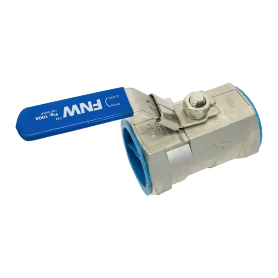
INSTALLATION, OPERATION & MAINTENANCE INSTRUCTIONS
3-Piece Threaded, Socket, Tube & Clamp End Ball Valves
INTRODUCTION
STORAGE
PRE-INSTALLATION NOTES
Page 1 of 6
Advertisement
Table of Contents

Related Manuals for FNW 1000 WOG


Summary of Contents for FNW 1000 WOG
- Page 1 Allow the water to drain out. 6. If the valve was supplied with an actuator, secondary support may be necessary. Contact FNW for recommendations.
- Page 2 12. To provide optimum service, the valve should be operated only in the fully open or fully closed position (on/off service). Throttling service is not recommended. 13. Use only FNW recommended spare parts for maintenance. 14. To ensure safety and to maintain warranty, never modify the valve in any way without prior approval from FNW.
- Page 3 NEVER REPLACE VALVE PACKING WHILE THE VALVE IS IN SERVICE. 4. Valves with body seals can be rebuilt by using a “Soft Goods” rebuild kit from FNW. Assembly and Disassembly For the following assembly and disassembly instructions, refer to Figure 1.
- Page 4 INSTALLATION, OPERATION & MAINTENANCE INSTRUCTIONS 3-Piece Threaded, Socket, Tube & Clamp End Ball Valves Disassembly A. Begin with the valve in the open position. B. Loosen the handle nut (13) and remove. C. Remove the handle (8). D. Bend the tab washer (11B) enough so that the gland nut (11) can be loosened. Remove the gland nut (11).
- Page 5 INSTALLATION, OPERATION & MAINTENANCE INSTRUCTIONS 3-Piece Threaded, Socket, Tube & Clamp End Ball Valves Body Bolt Torques (In-Lbs)* Table 1 Valve Size Valve Type/Class 1/4" 3/8" 1/2" 3/4" 1" 1-1/4" 1-1/2" 2" 2-1/2" 3" 4" 1000/800 WOG 86.74 86.74 86.74 104.08 104.08 130.11...
- Page 6 INSTALLATION, OPERATION & MAINTENANCE INSTRUCTIONS 3-Piece Threaded, Socket, Tube & Clamp End Ball Valves WARRANTY 1. LIMITED WARRANTY: Subject to the limitations expressed herein, Seller warrants that products manufactured by Seller shall be free from defects in design, material and workmanship under normal use for a period of one (1) year from installation but in no case shall the warranty period extend longer than eighteen months from the date of sale.
Need help?
Do you have a question about the 1000 WOG and is the answer not in the manual?
Questions and answers