Table of Contents
Advertisement
Quick Links
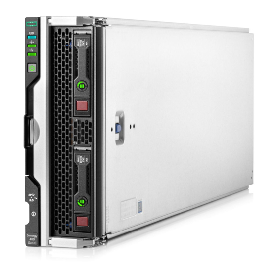
HPE Synergy 480 Gen10 Compute Module Maintenance
and Service Guide
Abstract
This document is for the person who installs, administers, and troubleshoots the HPE Synergy system. Hewlett Packard
Enterprise assumes you are qualified in the servicing of computer equipment and trained in recognizing hazards in
products with hazardous energy levels.
Part Number: 876832-008
Published: July 2020
Edition: 8
Advertisement
Table of Contents

Related Manuals for Hewlett Packard Enterprise Synergy 480 Gen10


Summary of Contents for Hewlett Packard Enterprise Synergy 480 Gen10
- Page 1 HPE Synergy 480 Gen10 Compute Module Maintenance and Service Guide Abstract This document is for the person who installs, administers, and troubleshoots the HPE Synergy system. Hewlett Packard Enterprise assumes you are qualified in the servicing of computer equipment and trained in recognizing hazards in products with hazardous energy levels.
- Page 2 Copyright 2017-2020 Hewlett Packard Enterprise Development LP Notices The information contained herein is subject to change without notice. The only warranties for Hewlett Packard Enterprise products and services are set forth in the express warranty statements accompanying such products and services.
-
Page 3: Table Of Contents
Contents Illustrated parts catalog....................6 Mechanical components......................................6 Access panel spare part....................................6 SFF drive blank spare part..................................7 DIMM baffle spare parts.....................................7 Front panel/drive cage assembly spare parts..........................7 Rear heatsink blank spare part................................7 Compute module end cap spare part..............................7 Mezzanine assembly spare part................................ - Page 4 Removing and replacing a compute module end cap..........................39 Removing and replacing the front panel/drive cage assembly......................40 Removing and replacing the M.2 SSD adapter board and flash drive ..................41 Removing and replacing a mezzanine option card...........................42 Removing and replacing a heatsink blank..............................43 Removing and replacing DIMM baffles................................
- Page 5 HPE Synergy firmware update resources..............................87 HPE Synergy document overview (documentation map)........89 Acronyms and abbreviations..................91 Websites..........................92 Support and other resources..................93 Accessing Hewlett Packard Enterprise Support............................93 Accessing updates........................................93 Remote support..........................................94 Warranty information......................................... 94 Regulatory information......................................94...
-
Page 6: Illustrated Parts Catalog
Illustrated parts catalog Mechanical components Hewlett Packard Enterprise continually improves and changes product parts. See the Hewlett Packard Enterprise PartSurfer website for complete and current supported parts information. Item Description Access panel spare part SFF HDD blank assembly spare part... -
Page 7: Sff Drive Blank Spare Part
Mezzanine assembly spare part Customer self repair: mandatory Description Spare part number Mezzanine assembly 801369-001 System components Hewlett Packard Enterprise continually improves and changes product parts. See the Hewlett Packard Enterprise PartSurfer website for complete and current supported parts information. Illustrated parts catalog... -
Page 8: System Battery Spare Part
Item Description System battery spare part DIMM spare parts HPE 16GB NVDIMM spare part HPE Persistent Memory module spare parts Processor heatsink spare parts Drive backplane spare parts Processor spare parts See Removal and replacement procedures for more information. System battery spare part Customer self repair: optional Description Spare part number... -
Page 9: Hpe 16Gb Nvdimm Spare Part
Description Spare part number 32-GB, 2Gx4, PC4-2666V-L 850881-001 64-GB, 2Gx4, PC4-2666V-L 850882-001 128-GB, 2Gx4, PC4-2666V-L 850883-001 Table 2: 2933 MT/s DIMMs Description Spare part number 8-GB, 1Rx8, PC4-2933Y-R P06186-001 16-GB, 1Rx4 PC4-2933Y-R P06187-001 16-GB, 2Rx8 PC4-2933Y-R P06188-001 16-GB, 1Gx8, PC4-2933Y-R, SAM P12416-001 32-GB, 2Rx4 PC4-2933Y-R P06189-001... -
Page 10: System Board Spare Parts
System board spare parts Customer self repair: optional Description Spare part number System board with base pan, compatible with First 870841-001 Generation Intel Xeon Scalable Processors System board with base pan, compatible with Second P08271-001 Generation Intel Xeon Scalable Processors Drive backplane spare parts Customer self repair: mandatory Description... - Page 11 Table 6: 61XX processors Description Spare part number Xeon-G 6126 12c 2.6-GHz 125W 875720-001 Xeon-G 6128 6c 3.4-GHz 115W 875721-001 Xeon-G 6130 16c 2.1-GHz 125W 874736-001 Xeon-G 6132 14c 2.6-GHz 133W 875722-001 Xeon-G 6134 8c 3.2-GHz 130W 875723-001 Xeon-G 6136 12c 3.0-GHz 150W 875724-001 Xeon-G 6138 20c 2.0-GHz 125W 874735-001...
-
Page 12: Second-Generation Intel Xeon Scalable Processor Spare Parts
Description Spare part number Xeon-P 8180 28c 2.5-GHz 205W 875731-001 Xeon-P 8180M 28c 2.5-GHz 205W 878089-001 Second-Generation Intel Xeon Scalable Processor spare parts Customer self repair: no All Intel Xeon processors in this HPE ProLiant server must have the same cache size, speed, number of cores, and rated maximum power consumption. - Page 13 Description Spare part number Xeon-G 5218R 20c 2.1-GHz 125W P19242-001 Xeon-G 5220 18c 2.2-GHz 125W P11613-001 Xeon-G 5220S 18c 2.6-GHz 125W P11627-001 Xeon-G 5220R 24c 2.1-GHz 150W P19241-001 Xeon-G 5222 4c 3.8-GHz 105W P11632-001 Table 11: 62XX processors Description Spare part number Xeon-G 6222v 20c 1.8-GHz 115W P12019-001 Xeon-G 6226 12c 2.7-GHz 125W...
-
Page 14: Compute Module Options
Xeon-P 8280M 28c 2.7-GHz 205W P11630-001 Xeon-P 8280L 28c 2.7-GHz 205W P11635-001 Compute module options Hewlett Packard Enterprise continually improves and changes product parts. For complete and current supported parts information, see the Hewlett Packard Enterprise PartSurfer website. Illustrated parts catalog... -
Page 15: M.2 Ssd Adapter Board Spare Part
Item Description M.2 SSD flash drive and adapter board spare parts HPE Trusted Platform Module 2.0 spare part Energy pack options spare parts Mezzanine option card (Type C) spare parts HPE Synergy Internal SATA board spare part Drive spare parts: SFF SAS HDD spare parts •... -
Page 16: Hpe Trusted Platform Module 2.0 Spare Part
Description Spare part number 480 GB SATA M.2 2280 MU DS 875851-001 480 GB SATA M.2 2280 RI DS 875855-001 960 GB SATA M.2 2280 RI DS 875856-001 960 GB SATA M.2 2280 MU DS 875852-001 HPE Trusted Platform Module 2.0 spare part Customer self repair: no Description Spare part number... -
Page 17: Hpe Synergy Internal Sata Board Spare Part
Description Spare part number HPE Synergy 480 NVIDIA Quadro M3000SE 869002-001 HPE Synergy 480 NVIDIA Tesla P6 (100W) 882006-001 This spare part number is for the graphics option card only. Spare part numbers for heatsink and adapter board are shown in Mechanical components. - Page 18 Description Spare part number 1.8 TB SAS 10,000-rpm, SC 512e HDD 791055-001 1.0 TB SAS 7,200-rpm, SC DS HDD 832984-001 1.0 TB SAS 7,200-rpm, SC 512e DS HDD 765872-001 2.0 TB SAS 7,200-rpm, SC 512e DS HDD 765873-001 SFF SATA HDD spare parts Customer self repair: mandatory Description Spare part number...
- Page 19 Description Spare part number 800 GB WI DS SC SSD P06602-001 800 GB WI SC DS SSD P09948-001 900 GB RI DS SC SSD P06596-001 960 GB MU SC VS DS SSD P10604-001 960 GB RI SC DS SSD P08608-001 960GB RI SC VS DS P10637-001 960 GB 12G RI SC SSD...
- Page 20 Description Spare part number 240 GB SATA 6G RI SC DS SSD 868924-001 240 GB SATA RI DS SC SSD 875652-001 240 GB SATA RI SC DS SSD P05319-001 240 GB SATA RI SC DS SSD P08565-001 400 GB SATA 6G WI SC DS SSD 872512-001 480 GB SATA RI SC DS SSD P05320-001...
- Page 21 Description Spare part number 1.92 TB SATA RI SC DS SSD P05322-001 1.92 TB SATA RI DS SC SSD P06573-001 1.92 TB SATA RI SC DS SSD P08572-001 1.92 TB SATA MU SC DS SSD P08625-001 1.92 TB SATA MU SC DS SSD P08694-001 1.92 TB SATA MU SC DS SSD P09912-001...
-
Page 22: Usb And Microsd Option Spare Parts
Dual Flash Adapter and SFF SATA uFF SSD spare parts Customer self repair: mandatory Description Spare part number Dual flash adapter spare 830452-001 uFF SSD 120 GB 831995-001 uFF SSD 340 GB 830453-001 USB and microSD option spare parts Customer self repair: mandatory Description Spare part number HPE Dual 8GB microSD EM USB device... -
Page 23: Customer Self Repair
Enterprise (or Hewlett Packard Enterprise service providers or service partners) identifies that the repair can be accomplished by the use of a CSR part, Hewlett Packard Enterprise will ship that part directly to you for replacement. There are two categories of CSR parts: Mandatory—Parts for which customer self repair is mandatory. - Page 24 (5) jours ouvrés. La pièce et sa documentation doivent être retournées dans l'emballage fourni. Si vous ne retournez pas la pièce défectueuse, Hewlett Packard Enterprise se réserve le droit de vous facturer les coûts de remplacement. Dans le cas d'une pièce CSR, Hewlett Packard Enterprise supporte l'ensemble des frais d'expédition et de retour, et détermine la société...
- Page 25 Per il servizio di garanzia per i soli componenti è obbligatoria la formula CSR che prevede la riparazione da parte del cliente. Se il cliente invece richiede la sostituzione ad Hewlett Packard Enterprise dovrà sostenere le spese di spedizione e di manodopera per il servizio.
- Page 26 Hewlett Packard Enterprise podrá cobrarle por el de sustitución. En el caso de todas sustituciones que lleve a cabo el cliente, Hewlett Packard Enterprise se hará cargo de todos los gastos de envío y devolución de componentes y escogerá la empresa de transporte que se utilice para dicho servicio.
- Page 27 Hewlett Packard Enterprise (ou fornecedores/parceiros da Hewlett Packard Enterprise) concluir que o reparo pode ser efetuado pelo uso de uma peça CSR, a Hewlett Packard Enterprise enviará a peça diretamente ao cliente. Há duas categorias de peças CSR: Obrigatória—Peças cujo reparo feito pelo cliente é...
- Page 28 Serviço de garantia apenas para peças A garantia limitada da Hewlett Packard Enterprise pode incluir um serviço de garantia apenas para peças. Segundo os termos do serviço de garantia apenas para peças, a Hewlett Packard Enterprise fornece as peças de reposição sem cobrar nenhuma taxa.
- Page 29 Customer self repair...
- Page 30 Customer self repair...
- Page 31 Customer self repair...
-
Page 32: Removal And Replacement Procedures
Removal and replacement procedures Required tools You need T-15 and T-30 Torx screwdrivers for performing procedures listed in this document. Safety considerations Before performing service procedures, review all the safety information. Preventing electrostatic discharge To prevent damaging the system, be aware of the precautions you must follow when setting up the system or handling parts. -
Page 33: Preparing The Compute Module
This symbol indicates the presence of electric shock hazards. The area contains no user or field serviceable parts. Do not open for any reason. WARNING: To reduce the risk of injury from electric shock hazards, do not open this enclosure. This symbol on an RJ-45 receptacle indicates a network interface connection. -
Page 34: Powering Down The Compute Module
Powering down the compute module Before powering down the compute module for any upgrade or maintenance procedures, perform a backup of the system and all data. Then, shut down, as appropriate, applications and operating systems. A successful shutdown is indicated by the system power LED displaying amber. -
Page 35: Installing The Compute Module
WARNING: To reduce the risk of personal injury from hot surfaces, allow the drives and the internal system components to cool before touching them. 4. Place the compute module on a flat, level work surface. CAUTION: To prevent damage to electrical components, properly ground the compute module before beginning any installation procedure. - Page 36 2. Prepare the compute module for installation by opening the compute module handle 3. Install the compute module. Slide the compute module until it is fully inserted in the enclosure slot. Rotate the handle until it latches. 4. Review the compute module front panel LEDs to determine the compute module status. For more information on the compute module LEDs, see "Component identification."...
-
Page 37: Removing And Replacing An Access Panel
Removing and replacing an access panel Procedure 1. Power down the compute module. 2. Remove the compute module. 3. Press the access panel release button. 4. Slide the access panel towards the rear of the compute module, and then lift to remove the panel. To replace the component, reverse the removal procedure. -
Page 38: Removing And Replacing A Drive
CAUTION: To prevent improper cooling and thermal damage, do not operate the compute module unless all bays are populated with either a component or a blank. To replace the component, reverse the removal procedure. Removing and replacing a drive Procedure 1. -
Page 39: Removing And Replacing An Sff Flash Adapter
Removing and replacing an SFF flash adapter CAUTION: Removing the SFF Flash Adapter also removes two uFF drives and might cause one or more logical drives to fail. Procedure 1. Power down the compute module. 2. Slide the adapter ejection handle release latch up. The handle will eject from the adapter. -
Page 40: Removing And Replacing The Front Panel/Drive Cage Assembly
To replace the component, reverse the removal procedure. More information Powering down the compute module Removing the compute module Removing and replacing the front panel/drive cage assembly Procedure 1. Power down the compute module. 2. Remove the compute module. 3. Place the compute module on a flat, level work surface. 4. -
Page 41: Removing And Replacing The M.2 Ssd Adapter Board And Flash Drive
To replace the component, reverse the removal procedure. Removing and replacing the M.2 SSD adapter board and flash drive Prerequisites To complete this procedure, you need a No. 1 Phillips screwdriver. Procedure Power down the compute module. Remove the compute module. Lay the compute module on a flat and level surface. -
Page 42: Removing And Replacing A Mezzanine Option Card
Uninstall the SSD adapter board. Lay the SSD adapter board on a flat surface. Remove the SSD flash drive screw, lift the drive at an angle, and then uninstall the SSD flash drive. 10. Repeat the SSD flash drive removal procedure for the second drive, as applicable. To replace the SSD flash drive or SSD adapter board, reverse the removal the procedure. -
Page 43: Removing And Replacing A Heatsink Blank
To replace the component, reverse the removal procedure. More information Powering down the compute module Removing the compute module Removing and replacing an access panel Removing and replacing a heatsink blank Procedure 1. Power down the compute module. 2. Remove the compute module. 3. -
Page 44: Removing And Replacing Dimm Baffles
To replace the component, reverse the removal procedure. Removing and replacing DIMM baffles Procedure 1. Power down the compute module. 2. Remove the compute module. 3. Place the compute module on a flat, level work surface. 4. Remove the access panel. 5. -
Page 45: Removing And Replacing Dimms
Removing and replacing DIMMs Procedure 1. Power down the compute module. 2. Remove the compute module. 3. Place the compute module on a flat, level work surface. 4. Remove the access panel. 5. Remove the DIMM baffles. NOTE: When accessing the right DIMM baffle, leave the energy pack option installed, and place the DIMM baffle upright on top of the heatsink. -
Page 46: Removing And Replacing An Nvdimm
Removing and replacing an NVDIMM CAUTION: Do not remove an NVDIMM when any LEDs on any NVDIMM in the system are illuminated. Removing an NVDIMM when an LED is illuminated might cause a loss of data. CAUTION: Electrostatic discharge can damage electronic components. Be sure you are properly grounded before beginning this procedure. -
Page 47: Nvdimm-Processor Compatibility
The NVDIMM-N Sanitize options are intended to meet the Purge level. For more information on sanitization for NVDIMMs, see the following sections in the HPE 16GB NVDIMM User Guide on the Hewlett Packard Enterprise website (http://www.hpe.com/info/nvdimm-docs): • NVDIMM sanitization policies •... -
Page 48: Nvdimm Relocation Guidelines
CAUTION: Failure to properly handle DIMMs can damage the DIMM components and the system board connector. For more information, see the DIMM handling guidelines in the troubleshooting guide for your product on the Hewlett Packard Enterprise website: • HPE ProLiant Gen10 (https://www.hpe.com/info/gen10-troubleshooting) •... -
Page 49: Configuring The Compute Module For Nvdimms
Configuring the compute module for NVDIMMs After installing NVDIMMs, configure the compute module for NVDIMMs. For information on configuring settings for NVDIMMs, see the HPE 16GB NVDIMM User Guide on the Hewlett Packard Enterprise website (http://www.hpe.com/ info/nvdimm-docs). The compute module can be configured for NVDIMMs using either of the following: •... - Page 50 To identify the HPE Persistent Memory modules installed in the compute module, see HPE Persistent Memory module label identification. Procedure 1. Observe the following alerts: CAUTION: Electrostatic discharge can damage electronic components. Be sure you are properly grounded before beginning this procedure. CAUTION: Failure to properly handle HPE Persistent Memory modules can damage the component and the system board connector.
-
Page 51: Hpe Persistent Memory Module-Processor Compatibility
HPE Persistent Memory, as well as evaluate and monitor the compute module memory configuration layout. For more information, see the HPE Persistent Memory User Guide on the Hewlett Packard Enterprise website (https:// www.hpe.com/info/persistentmemory-docs). -
Page 52: Hpe Persistent Memory Module Sanitization
If HPE Persistent Memory modules are encrypted with remote key management, enroll the HPE iLO in the key management server to provide access to the data on the HPE Persistent Memory modules. For more information, see the HPE Persistent Memory User Guide on the Hewlett Packard Enterprise website (https:// www.hpe.com/info/persistentmemory-docs). -
Page 53: Hpe Smart Storage Battery
• Clear: Overwrite user-addressable storage space using standard write commands; might not sanitize data in areas not currently user-addressable (such as bad blocks and over-provisioned areas). • Purge: Overwrite or erase all storage space that might have been used to store data using dedicated device sanitize commands, such that data retrieval is "infeasible using state-of-the-art laboratory techniques."... -
Page 54: Minimum Firmware Versions
Minimum firmware versions Product Minimum firmware version 2.00 HPE Synergy 480 Gen10 Compute Module system ROM HPE Smart Array SR controllers 1.90 Removing and replacing the Energy pack option Procedure 1. Power down the compute module. 2. Remove the compute module. -
Page 55: Removing And Replacing The Drive Backplane
3. Place the compute module on a flat, level work surface. 4. Remove the access panel. 5. Remove all drives from the drive cage. 6. Remove the front panel/drive cage assembly. 7. Remove the storage controller. To replace the component, reverse the removal procedure. More information Powering down the compute module Removing the compute module... -
Page 56: Removing And Replacing The Internal Sata Board
6. Remove the front panel/drive cage assembly. 7. If you are removing the premium backplane, disconnect the premium drive backplane cable. 8. Remove the drive backplane from the front panel/drive cage assembly. The cable shown in the image below is not required for a standard drive backplane. CAUTION: To avoid damaging the connector housing component, be sure to orient the drive backplane connectors so that they are facing the drive slots. -
Page 57: Removing And Replacing The System Battery
To replace the component, reverse the removal procedure. Removing and replacing the system battery If the compute module no longer automatically displays the correct date and time, then replace the battery that provides power to the real-time clock. Under normal use, battery life is 5 to 10 years. WARNING: The computer contains an internal lithium manganese dioxide, a vanadium pentoxide, or an alkaline battery pack. -
Page 58: Removing And Replacing The Mezzanine Assembly
IMPORTANT: Replacing the system board battery resets the system ROM to its default configuration. After replacing the battery, use BIOS/Platform Configuration (RBSU) in the UEFI System Utilities to reconfigure the system. To replace the component, reverse the removal procedure. For more information about battery replacement or proper disposal, contact an authorized reseller or an authorized service provider. -
Page 59: Removing And Replacing The System Board
To replace the component: 1. Align and install the mezzanine assembly on the system board. 2. Install all mezzanine option cards removed from the compute module. 3. Install the access panel. 4. Install the compute module. Removing and replacing the system board Prerequisites If HPE Persistent Memory modules are installed in the compute module and are encrypted with local key management, do one of the following:... - Page 60 Export a password file to a USB key. Hewlett Packard Enterprise recommends exporting the password file to a USB key. For more information, see the HPE Persistent Memory User Guide on the Hewlett Packard Enterprise website (https:// www.hpe.com/info/persistentmemory-docs). To complete this procedure, you need access to the following: •...
- Page 61 18. Disassemble the heatsink blank, and then use the dust cap to cover the processor socket on the system board. 19. Remove the processor heatsink assembly. For more information, see Migrating a processor heatsink assembly to a replacement system board. 20.
-
Page 62: Re-Entering The Server Serial Number And Product Id
IMPORTANT: Before attaching the graphics expansion module, set system maintenance switch 9 on the compute module to the On position. Failure to do so results in an HPE OneView detection failure, and the expansion module will be inoperable. To locate the system maintenance switch, see "System board components."... -
Page 63: Unassigning A Server Profile Using Hpe Oneview
4. In the Server hardware box, select the appropriate server. 5. Click OK. Migrating a processor-heatsink assembly to a replacement system board Prerequisites Before performing this procedure, Hewlett Packard Enterprise recommends identifying the processor-heatsink assembly components. Removal and replacement procedures... - Page 64 Procedure Observe the following alerts. CAUTION: When handling the heatsink, always hold it along the top and bottom of the fins. Holding it from the sides can damage the fins. CAUTION: To avoid damage to the processor or system board, only authorized personnel should attempt to replace or install the processor in this compute module.
- Page 65 c. Align the processor-heatsink assembly with the alignment posts and gently lower it down until it sits evenly on the socket. The heatsink alignment posts are keyed. The processor will only install one way. A standard heatsink is shown. Your heatsink might look different. d.
-
Page 66: Hpe Trusted Platform Module 2.0 Gen10 Option
USB connector and is configured upon boot. To locate the internal USB connector, see "System board components." For more information, see the Dual 8Gb microSD EM USB storage device documentation on the Hewlett Packard Enterprise website. More information System board components... -
Page 67: Component Identification
Component identification Front panel components Item Description Drive bay 1 Drive bay 2 External USB iLO Service Port (169.254.1.2) - located behind the Serial label pull tab External USB 3.0 connector (located behind the Serial label pull tab) Compute module handle release latch Compute module handle If uFF drives (the SFF Flash Storage Adapter) are installed in the drive bays, the drive bay numbering is different. -
Page 68: Front Panel Leds And Buttons
Front panel LEDs and buttons Item Description Status UID LED Solid blue = Activated Flashing blue (1 Hz/cycle per sec) = Remote management or firmware upgrade in progress Off = Deactivated Health status LED Solid green = Normal Flashing green (1 Hz/cycle per sec) = iLO is rebooting. Flashing amber = System degraded Flashing red (1 Hz/cycle per sec) = System critical Table Continued... -
Page 69: Drive Numbering
Item Description Status Mezzanine NIC status LED Solid green= Link on any Mezzanine NIC Flashing green= Activity on any Mezzanine NIC Off = No link or activity on any Mezzanine NIC Power On/Standby button and system power Solid green = System on Flashing green (1 Hz/cycle per sec) = Performing power on sequence Solid amber = System in standby... -
Page 70: Smart Carrier (Sc) Drive Led Definitions
Item Hard drive/SSD bay uFF drive bay numbering NVMe drive bay numbering numbering 1 and 101 2 and 102 Smart Carrier (SC) drive LED definitions Item Status Definition Locate Solid blue The drive is being identified by a host application. Flashing blue The drive carrier firmware is being updated or requires an update. -
Page 71: Sff Flash Adapter Components And Led Definitions
Item Status Definition Solid amber The drive has failed. The drive is not configured by a RAID controller or a spare drive. SFF flash adapter components and LED definitions Item Component Description Locate • Off—Normal • Solid blue—The drive is being identified by a host application. •... -
Page 72: Smart Carrier Nvme (Scn) Drive Led Definitions
Item Component Description Drive status LED • Off—The drive is not configured by a RAID controller or a spare drive. • Solid green—The drive is a member of one or more logical drives. • Flashing green (4 Hz)—The drive is operating normally and has activity. -
Page 73: System Board Components
Item Status Definition Drive Solid green The drive is a member of one or more logical drives. status The drive is doing one of the following: Flashing green • Rebuilding • Performing a RAID migration • Performing a stripe size migration •... -
Page 74: System Maintenance Switch
Item Description System battery Internal USB 3.0 connector Processor 1 DIMM slots (12) Processor 2 DIMM slots (12) Energy pack option connector Mezzanine connectors (M1, M2, and M3) Management/power connector System maintenance switch External USB iLO Service Port (169.254.1.2) - located behind the Serial label pull tab External USB 3.0 connector (located behind the Serial label pull tab) MicroSD connector Drive backplane connector... -
Page 75: Processor, Heatsink, And Socket Components
To access redundant ROM, set S1, S5 and S6 to On. Set swtich S9 to On for GPU expansion options Processor, heatsink, and socket components Item Description Heatsink nuts Processor carrier Pin 1 indicator Heatsink guide/keying feature Alignment post Symbol also on the processor and frame. Mezzanine connector definitions Component identification... -
Page 76: Dimm Slot Locations
NOTE: Hewlett Packard Enterprise recommends that you install P416ie-m on mezzanine 1. * When an NVIDIA Tesla M6 GPU FIO Adapter for HPE Synergy 480 Gen10 compute module is installed in mezzanine connector 1, mezzanine connector 2 is not available for additional mezzanine cards. - Page 77 Item Description Example Capacity 8 GB 16 GB 32 GB 64 GB 128 GB Rank 1R = Single rank 2R = Dual rank 4R = Quad rank 8R = Octal rank Data width on DRAM x4 = 4-bit x8 = 8-bit x16 = 16-bit Memory generation PC4 = DDR4...
-
Page 78: Nvdimm Identification
L = LRDIMM (load reduced) E = Unbuffered ECC (UDIMM) For more information about product features, specifications, options, configurations, and compatibility, see the HPE DDR4 SmartMemory QuickSpecs on the Hewlett Packard Enterprise website (https://www.hpe.com/support/ DDR4SmartMemoryQS). NVDIMM identification NVDIMMs are supported only when first-generation Intel Xeon Scalable processors are installed on the compute module. -
Page 79: Nvdimm Led Identification
RDIMM (registered) Other — For more information about NVDIMMs, see the product QuickSpecs on the Hewlett Packard Enterprise website (http:// www.hpe.com/info/qs). NVDIMM 2D Data Matrix barcode The 2D Data Matrix barcode is on the right side of the NVDIMM label and can be scanned by a cell phone or other device. - Page 80 NVDIMM-N LED combinations State Definition NVDIMM-N Power LED NVDIMM-N Function LED (green) (blue) AC power is on (12V rail) but the NVM controller is not working or not ready. AC power is on (12V rail) and the NVM controller is ready. AC power is off or the battery is off (12V rail off).
-
Page 81: Hpe Persistent Memory Module Label Identification
128 GB 256 GB 512 GB QR code Includes part number and serial number For more information about product features, specifications, options, configurations, and compatibility, see the product QuickSpecs on the Hewlett Packard Enterprise website (https://www.hpe.com/support/persistentmemoryQS). Enterprise Midline USB Component identification... -
Page 82: Leds
Item Description microSD card slot microSD1 card microSD2 card LEDs Item Description Status Power LED Green: Device is on and at least one microSD card is functioning. Red: Both microSD cards have failed. SD2 LED On: microSD card has failed. Off: microSD card is healthy. -
Page 83: Cabling
Cabling configurations and requirements vary depending on the product and installed options. For more information about product features, specifications, options, configurations, and compatibility, see the product QuickSpecs on the Hewlett Packard Enterprise website (http://www.hpe.com/info/qs). Energy pack option cabling P416ie-m Smart Array Controller cabling... - Page 84 Port 3i connector Mezzanine option card in mezzanine slot 1 SAS cable connector Cabling...
-
Page 85: Specifications
** Storage maximum humidity of 95% is based on a maximum temperature of 45°C (113°F). † Maximum storage altitude corresponds to a minimum pressure of 70 kPa (10.1 psia). Compute module physical specifications The following details physical specifications for the HPE Synergy 480 Gen10 compute module. Specification Value Height 63.60 mm (2.50 in) -
Page 86: Hpe Synergy Documentation Resources
HPE Synergy documentation resources The Hewlett Packard Enterprise Information Library (https://www.hpe.com/info/synergy-docs) provides a comprehensive, one stop location for all HPE Synergy documentation, including installation instructions, user guides, maintenance and service guides, best practices, and links to additional resources. The Library supports filtering to improve findability. -
Page 87: Hpe Synergy Firmware Update Resources
Document: Provides: Support Matrix The latest software and firmware requirements, supported hardware, and configuration maximums for HPE Synergy Image Streamer. User Guide The OS deployment process using HPE Synergy Image Streamer, features of HPE Synergy Image Streamer, and purpose and life cycle of HPE Synergy Image Streamer artifacts. - Page 88 Identifying Upgrade Paths Information on how to use the upgrade path table. HPE Synergy Resources A list of key resources for HPE Synergy. Hewlett Packard Enterprise A solution level library for all HPE Synergy product documentation. Information Library HPE Synergy documentation resources...
-
Page 89: Hpe Synergy Document Overview (Documentation Map)
HPE Synergy document overview (documentation map) The Hewlett Packard Enterprise Information Library (https://www.hpe.com/info/synergy-docs) provides a comprehensive, one stop location for all HPE Synergy documentation, including installation instructions, user guides, maintenance and service guides, best practices, and links to additional resources. The Library supports filtering to improve findability. - Page 90 Installing hardware Maintaining • HPE Synergy Start Here Poster (included with frame) • Product maintenance and service guides • HPE Synergy 12000 Frame Setup and Installation • HPE OneView for HPE Synergy Firmware and Driver Guide Update Guide • • Rack Rails Installation Instructions for the HPE Synergy HPE OneView Help for HPE Synergy 12000 Frame (included with frame)
-
Page 91: Acronyms And Abbreviations
Acronyms and abbreviations enterprise mainstream (HPE SSD endurance class) electrical nonmetallic tubing enterprise value (HPE SSD endurance class) Integrated Lights-Out Integrated Management Log keyboard, video, and mouse NVMe Non-Volatile Memory Express POST Power-On Self-Test serial attached SCSI SATA serial ATA small form factor Trusted Platform Module UEFI... -
Page 92: Websites
Websites General websites Hewlett Packard Enterprise Information Library https://www.hpe.com/info/EIL Single Point of Connectivity Knowledge (SPOCK) Storage compatibility matrix https://www.hpe.com/storage/spock Storage white papers and analyst reports https://www.hpe.com/storage/whitepapers For additional websites, see Support and other resources. Websites... -
Page 93: Support And Other Resources
• For live assistance, go to the Contact Hewlett Packard Enterprise Worldwide website: https://www.hpe.com/info/assistance • To access documentation and support services, go to the Hewlett Packard Enterprise Support Center website: https://www.hpe.com/support/hpesc Information to collect • Technical support registration number (if applicable) •... -
Page 94: Remote Support
HPE Networking Products https://www.hpe.com/support/Networking-Warranties Regulatory information To view the regulatory information for your product, view the Safety and Compliance Information for Server, Storage, Power, Networking, and Rack Products, available at the Hewlett Packard Enterprise Support Center: https://www.hpe.com/support/Safety-Compliance-EnterpriseProducts Support and other resources... -
Page 95: Documentation Feedback
Documentation feedback Hewlett Packard Enterprise is committed to providing documentation that meets your needs. To help us improve the documentation, send any errors, suggestions, or comments to Documentation Feedback (docsfeedback@hpe.com). When submitting your feedback, include the document title, part number, edition, and publication date located on the front cover of the document.
Need help?
Do you have a question about the Synergy 480 Gen10 and is the answer not in the manual?
Questions and answers