
Subscribe to Our Youtube Channel
Related Manuals for Flybox EFC57-P


Summary of Contents for Flybox EFC57-P
- Page 1 ® Electronic Flap Controller EFC57-P / EFC-P Revision# 3.4 03/12/2019 For firmware version 1.5...
- Page 2 Installation and User Manual, Safety Instructions and Warning Booklet This product is not TSO’d and cannot be installed into traditional FAA Part 23 and similarly Type-Certificate Aircraft Document A2019EFC Revision#3.4, 12/2019 For firmware version 1.5 This booklet is suitable for printing in A5 format.
- Page 3 SECTIONS INTRODUCTION IMPORTANT NOTICE AND WARNINGS INDEX MECHANICAL INSTALLATION TRANSDUCER & ACTUATOR INSTALLATION ELECTRICAL INSTALLATION USE OF THE INSTRUMENT TECHNICAL SPECIFICATIONS...
- Page 4 FLYBOX ® Introduction Thank you for purchasing a Flybox® product. We hope it fully satisfy you and makes your flights pleasant and secure. Developing EFC57-P and EFC-P, hereinafter referred to as the EFCX, our intent was to create a compact and lightweight flap controller, easy to install and use and reliable.
- Page 5 Therefore, we strongly suggest to double check all of the electronic instruments available on the aircraft and to turn them on to verify they function correctly. EFC57-P/EFC-P - User’s manual - Installation and User Manual, Safety Instructions and Warning Booklet...
- Page 6 EFCX may result in unexpected movements of the flaps. In this situation you must immediately disable the EFCX by turning the switch in the “MANUAL” position (see chap.4.4 “Use in MANUAL mode”). EFC57-P/EFC-P - User’s manual - Installation and User Manual, Safety Instructions and Warning Booklet...
- Page 7 CAUTION: Using this instrument over the maximum allowable ranges can cause malfunction or wrong indications. EFC57-P/EFC-P - User’s manual - Installation and User Manual, Safety Instructions and Warning Booklet Rev. 3.4...
- Page 8 ® Important notices & warnings NOTE: Flybox Avionics reserves the right to change or improve its products as well as terms, conditions, and notices under which their products are offered without prior notice. NOTE: The Installation and User Manual, Safety Instructions and Warning Booklet will be updated annually if needed.
-
Page 9: Table Of Contents
Wiring diagram for actuator with internal limit switches Wiring diagram for actuator with internal limit switches and external wires Wirings check EFC57-P/EFC-P - User’s manual - Installation and User Manual, Safety Instructions and Warning Booklet Rev. 3.4... - Page 10 Use in AUTOMATIC mode Use in MANUAL mode Troubleshooting and error code SECTION 5 Technical specifications Warranty TERM OF USE AND DISCLAIMER …………… …… EFC57-P/EFC-P - User’s manual - Installation and User Manual, Safety Instructions and Warning Booklet Rev. 3.4...
-
Page 11: Mechanical Installation
FLYBOX ® Mechanical installation SECTION 1 1.1 MECHANICAL INSTALLATION Rectangular version (EFC-P) panel cut-out Dimensions in millimeters EFC57-P/EFC-P - User’s manual - Installation and User Manual, Safety Instructions and Warning Booklet Rev. 3.4... -
Page 12: 2"¼ Round Panel Version
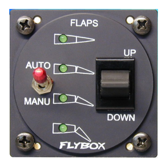
FLYBOX ® Mechanical installation 2”1/4 round version (EFC57-P) Dimensions in millimeters EFC57-P/EFC-P - User’s manual - Installation and User Manual, Safety Instructions and Warning Booklet Rev. 3.4... -
Page 13: Transducer Installation
(motor) and the transducer (potentiometer) which allows the EFCX to know the actual flaps position. Example of mechanical installations actuator-transducer EFC57-P/EFC-P - User’s manual - Installation and User Manual, Safety Instructions and Warning Booklet Rev. 3.4... - Page 14 - The transducer must be centered over the actuator's travel so that it isn't possible to exit from the limits, with consequently damage to the position's transducer. EFC57-P/EFC-P - User’s manual - Installation and User Manual, Safety Instructions and Warning Booklet...
-
Page 15: Actuator Installation
“Manual” mode of the EFCX) can cause mechanical damage if he don't stop exactly when the flaps have reached the up and down positions. EFC57-P/EFC-P - User’s manual - Installation and User Manual, Safety Instructions and Warning Booklet Rev. 3.4... - Page 16 10 Kohm transducer, verify that the stroke that you are going to use provide at least a variation of half the transducer's resistance, i.e. 5 Kohm. EFC57-P/EFC-P - User’s manual - Installation and User Manual, Safety Instructions and Warning Booklet...
-
Page 17: Electrical Installation
In the backpanel there is a 10-poles plug connector (model: MOLEX Mini-Fit JR.); the corresponding socket connector is delivered with your EFCX. Backpanel plug Socket view (from wire'insertion side) EFC57-P/EFC-P - User’s manual - Installation and User Manual, Safety Instructions and Warning Booklet Rev. 3.4... - Page 18 CAUTION: The EFCX must be turned off in case of start with booster. Open the corresponding breaker before starting. EFC57-P/EFC-P - User’s manual - Installation and User Manual, Safety Instructions and Warning Booklet Rev. 3.4...
-
Page 19: Wiring Diagram For Actuator With No Internal Limit Switches
If the actuator used has integrated limit switches and wiring (no external wires) use the wiring diagram above, connecting pin #1 and #6 of the EFCX connector directly to the actuator. EFC57-P/EFC-P - User’s manual - Installation and User Manual, Safety Instructions and Warning Booklet... -
Page 20: Wiring Diagram For Actuator With Internal Limit Switches And External Wires
Wiring diagram for actuator with internal limit switches and external wires. Note that the common contact of the limit switches is connected to pin #9. EFC57-P/EFC-P - User’s manual - Installation and User Manual, Safety Instructions and Warning Booklet Rev. 3.4... -
Page 21: Wirings Check
If this doesn't occur, or if the EFCX does not work correctly, swap the two wires on pins #3 and #5 of the EFCX connector. EFC57-P/EFC-P - User’s manual - Installation and User Manual, Safety Instructions and Warning Booklet... - Page 22 Operating this switch without pulling the red knob will cause it to break. EFC57-P/EFC-P - User’s manual - Installation and User Manual, Safety Instructions and Warning Booklet...
- Page 23 ● Power on the EFCX and wait 10 seconds until the LED1 and the LED4 come on steady. ● Release the U/D switch (LED1 and LED4 start flashing), indicating that the device is in programming mode. EFC57-P/EFC-P - User’s manual - Installation and User Manual, Safety Instructions and Warning Booklet...
- Page 24 If the EFCX is powered on the first time without enter in the programming mode the four LED will simultaneously flash. The positions remains stored in memory also without power supply. EFC57-P/EFC-P - User’s manual - Installation and User Manual, Safety Instructions and Warning Booklet Rev. 3.4...
- Page 25 Pressing the U/D switch in the UP position for more than 1 second move automatically the flaps to the first position (regardless of the current position). EFC57-P/EFC-P - User’s manual - Installation and User Manual, Safety Instructions and Warning Booklet...
- Page 26 To control the flaps simply use the U/D switch: press and hold in a position (UP or DOWN) and release when the motor have reached the desired position. EFC57-P/EFC-P - User’s manual - Installation and User Manual, Safety Instructions and Warning Booklet...
- Page 27 ● detected an over-current condition. Check that wirings of the actuator motor have no short circuits or check that the actuator is working correctly. EFC57-P/EFC-P - User’s manual - Installation and User Manual, Safety Instructions and Warning Booklet Rev. 3.4...
- Page 28 ● Power requirements: 12 ~ 20 V=, 80 mA. ● Maximum current supplied to the motor: 7 Ampere. ● Operating temperature range: -20 ~ +70 °C. ● Relative humidity: 10% ~ 90% without condensation. EFC57-P/EFC-P - User’s manual - Installation and User Manual, Safety Instructions and Warning Booklet...
- Page 29 Products is not intended to be used. Flybox®, after verification of the complaint and confirmation that the defect is covered by warranty, at its sole discretion, will either replace or repair the Products at no costs for the customer.
- Page 30 Use of this product is unauthorized in any jurisdiction that does not give effect to all provisions of these terms and conditions, including without limitation this paragraph. EFC57-P/EFC-P - User’s manual - Installation and User Manual, Safety Instructions and Warning Booklet Rev.
- Page 31 WARNING: All photos, data, drawings, instruments layouts, technical solutions and data representation you find in this document or watching at FLYBOX® instruments working and/or you can access by means of any other media, including web sites, are sole property of MICROEL s.r.l., cannot be copied or imitate without a written permission of MICROEL s.r.l.
- Page 32 MICROEL s.r.l. Via Mortara 192-194 27038 Robbio (PV) - ITALY Tel +39-0384-670602 - Fax +39-0384-671830 www.flyboxavionics.it...
Need help?
Do you have a question about the EFC57-P and is the answer not in the manual?
Questions and answers