
Related Manuals for Flybox EFC-P


Summary of Contents for Flybox EFC-P
- Page 1 ® Electronic Flap Controller EFC-P Revision# 3.1 17/7/2015 For firmware version 1.5...
- Page 2 Page intentionally left blank...
- Page 3 SECTIONS MECHANICAL INSTALLATION TRANSDUCER & ACTUATOR INSTALLATION ELECTRICAL INSTALLATION USE OF THE INSTRUMENT TECHNICAL SPECIFICATIONS...
- Page 4 Thank you for purchasing a Flybox® product. We hope it fully satisfy you and makes your flights pleasant and secure. Developing EFC-P, our intent was to create a compact and lightweight flap controller, easy to install and use. SYMBOLS USED IN THE MANUAL NOTE: Used to highlight important informations.
- Page 5 FLYBOX ® Important notices & warnings NOTE: Although the EFC-P has been heavily tested to ensure the maximum safety in every condition, the correct operation depends also by installation and wiring, that must be accurately made and verified reading completely this manual.
- Page 6 FLYBOX ® Important notices & warnings WARNING: the EFC-P must be turned off in case of start with booster. open the corresponding breaker before starting. warranty shall not apply for damage to the EFC-P for this reason. WARNING: The EFC-P is attached directly to the flaps...
- Page 7 SECTION 3 Electrical installation Wiring diagram for actuator with no internal limit switches Wiring diagram for actuator with internal limit switches Wiring diagram for actuator with internal limit switches and external wires Wirings check EFC-P - User’s manual Rev. 3.1...
- Page 8 FLYBOX ® Index Panel indicators and commands Operation instructions Use in AUTOMATIC mode Use in MANUAL mode Troubleshooting and error code SECTION 5 Technical specifications Warranty EFC-P - User’s manual Rev. 3.1...
-
Page 9: Mechanical Installation
FLYBOX ® Mechanical installation SECTION 1 1.1 MECHANICAL INSTALLATION Ractangular panel version (EFC-P) Dimensions in millimeters Panel cut-out EFC-P - User’s manual Rev. 3.1... - Page 10 FLYBOX ® Mechanical installation 2”1/4 round panel version (EFC57-P) Dimensions in millimeters EFC-P - User’s manual Rev. 3.1...
-
Page 11: Section 2 2.1 Transducer Installation
(only if using actuator without integrated transducer) The installation consists in the mechanical coupling between the flaps actuator (motor) and the transducer (potentiometer) which permits the EFC-P to know the actual flaps position. Example of mechanical installations actuator-transducer EFC-P - User’s manual... - Page 12 - The electrical resistance of the transducer must be from 1 to 10 Kohm. - The transducer must be centered over the actuator's travel so that it isn't possible to exit from the limits, with consequently damage to the position's transducer. EFC-P - User’s manual Rev. 3.1...
-
Page 13: Actuator Installation
(for example using “Manual” mode of the EFC-P) can cause mechanical damage if he don't stop exactly when the flaps have reached the up and down positions. - Page 14 For example if you choose an actuator with 10 Kohm transducer, verify that the stroke that you are going to use provide at least a variation of half the transducer's resistance, i.e. 5 Kohm. EFC-P - User’s manual Rev. 3.1...
-
Page 15: Section 3 3.1 Electrical Installation
Electrical installation SECTION 3 3.1 ELECTRICAL INSTALLATION In the backpanel there is a 10-poles plug connector (model: MOLEX Mini-Fit JR.); the corresponding socket connector is delivered with your EFC-P. Backpanel plug Socket view (from wire'insertion side) EFC-P - User’s manual... - Page 16 EFC-P side and leaves disconnected the shield on the actuator side. WARNING: Voltage peaks higher than 15 Volt on the supply line can damage the device. WARNING: The EFC-P must be turned off in case of start with booster. Open the corresponding breaker before starting. EFC-P - User’s manual...
-
Page 17: Wiring Diagram For Actuator With No Internal Limit Switches
INTERNAL LIMIT SWITCHES If the actuator used has integrated limit switches and wiring (no external wires) use the wiring diagram above, connecting pin #1 and #6 of the EFC-P connector directly to the actuator. EFC-P - User’s manual Rev. 3.1... -
Page 18: Internal Limit Switches And External Wires
If the actuator used has 3 wires for the limit switches connection, probably one wire is the common contact for the limit switches, so the wiring diagram to the EFC-P is the following: Wiring diagram for actuator with internal limit switches and external wires. -
Page 19: Wirings Check
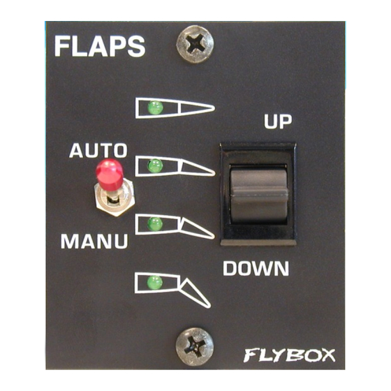
If this doesn't occur, or if the EFC-P does not work correctly, swap the two wires on pins #3 and #5 of the EFC-P connector. - Page 20 U/D switch (Auto/Manual) (Up/Down) LED 3 LED 4 NOTE: The Auto/Manual switch has a safety lock to avoid accidental operation: it must first pulled on the outside and then moved to the desired position. EFC-P - User’s manual Rev. 3.1...
- Page 21 “Automatic” position, then press and hold the U/D switch in the “UP” position.. ● Power on the EFC-P and wait 10 seconds until the LED1 and the LED4 come on steady. ● Release the U/D switch (LED1 and LED4 start flashing).
- Page 22 NOTE: If the EFC-P is powered on the first time without enter in the programming mode the four LED will simultaneously flash. The positions remains stored in memory also without power supply.
- Page 23 LED turn off and the third turn on. The flaps have reached the selected position and the EFC-P return to steady state, waiting for another command.
- Page 24 U/D switch. To control the flaps simply use the U/D switch: press and hold in a position (UP or DOWN) and release when the motor have reached the desired position. EFC-P - User’s manual Rev. 3.1...
- Page 25 All the four LEDs flashing: no positions' programming ● have been made (see chap. 4.2) LED1 and LED2 flashing: it means that the EFC-P try ● to move the motor but there is no feedback from the transducer: can be a wrong connections on the motor's wiring or on the transducer's wiring.
-
Page 26: Technical Specifications
● Power requirements: 12 ~ 20 V=, 80 mA. ● Maximum current supplied to the motor: 7 Ampere. ● Operating temperature range: -20 ~ +70 °C. ● Relative humidity: 10% ~ 90% without condensation. EFC-P - User’s manual Rev. 3.1... -
Page 27: Warranty
Updated chap.4.2 WARNING: All photos, data, drawings, instruments layouts, technical solutions and data representation you find in this document or watching at FLYBOX® instruments working and/or you can access by means of any other media, including web sites, are sole property of MICROEL s.r.l., cannot be copied or imitate without a written permission of MICROEL s.r.l. - Page 28 MICROEL s.r.l. Via Mortara 192-194 27038 Robbio (PV) - ITALY Tel +39-0384-670602 - Fax +39-0384-671830 www.flyboxavionics.it...
Need help?
Do you have a question about the EFC-P and is the answer not in the manual?
Questions and answers