NETGEAR GS305EP User Manual
Gigabit ethernet smart managed plus switches
Hide thumbs
Also See for GS305EP:
- Installation manual (2 pages) ,
- Installation manual (6 pages) ,
- User manual (98 pages)

Related Manuals for NETGEAR GS305EP


Summary of Contents for NETGEAR GS305EP
- Page 1 User Manual Gigabit Ethernet Smart Managed Plus Switches Models • GS305EP • GS305EPP • GS308EP • GS308EPP NETGEAR, Inc. December 2020 350 E. Plumeria Drive 202-12193-01 San Jose, CA 95134, USA...
- Page 2 See the regulatory compliance document before connecting the power supply. For NETGEAR’s Privacy Policy, visit https://www.netgear.com/about/privacy-policy. By using this device, you are agreeing to NETGEAR’s Terms and Conditions at https://www.netgear.com/about/terms-and-conditions. If you do not agree, return the device to your place of purchase within your return period.
-
Page 3: Table Of Contents
Chapter 1 Hardware Related documentation...............7 Switch package contents..............7 Supported switch models..............7 Model GS305EP, GS305EPP, GS308EP, GS308EPP LEDs....7 Switch label....................8 Safety instructions and warnings............9 Chapter 2 Install and Access the Switch in Your Network Set up the switch in your network and power on the switch..13 Methods to discover or access the switch........13... - Page 4 Deactivate a port-based or 802.1Q VLAN mode and delete all VLANs....................55 Chapter 5 Manage the Switch in Your Network Manage NETGEAR Switch Discovery Protocol.......58 Set up static link aggregation............58 Set up a link aggregation group..........59 Make a link aggregation connection...........60 Enable a link aggregation group..........60...
- Page 5 PoE troubleshooting suggestions............88 Appendix A Factory Default Settings and Technical Specifications Factory default settings..............90 Technical specifications..............91 Model GS305EP and GS308EP technical specifications...91 Model GS305EPP and GS308EPP technical specifications..91 Appendix B Additional Switch Discovery and Access Information Access the switch from any computer..........94...
-
Page 6: Chapter 1 Hardware
Hardware This user manual is for the NETGEAR Gigabit Ethernet Smart Managed Plus Switches. For a list of switch models that are supported by this manual, see Supported switch models on page 7. This chapter covers the following topics: • Related documentation •... -
Page 7: Related Documentation
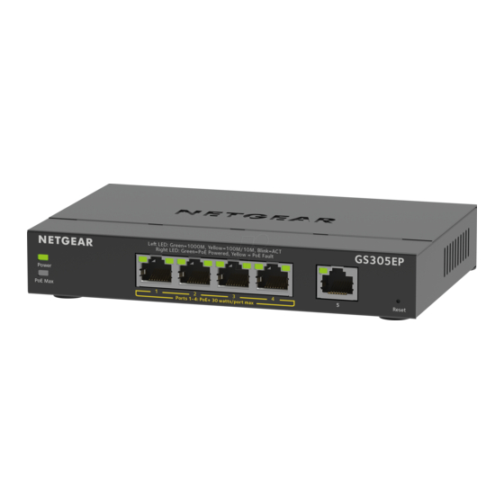
This section describes the LED designations of models GS305EP, GS305EPP, GS308EP, GS308EPP. The port LEDs are located above the ports. On models GS305EP and GS305EPP, ports 1 through 4 are PoE+ ports. Port 5 is an Ethernet (uplink) port. Hardware... -
Page 8: Switch Label
Gigabit Ethernet Smart Managed Plus Switches Series 3XXEP and 3XXEPP On models GS308EP and GS308EPP, all ports 1 through 8 are PoE+ ports. Table 2. Model GS305EP, GS305EPP, GS308EP, GS308EPP LEDs on the front panel Description Power LED Solid green: The switch is powered on and operating normally. -
Page 9: Safety Instructions And Warnings
Before connecting the product to outdoor cables or devices, see https://kb.netgear.com/000057103 for additional safety and warranty information. Failure to follow these guidelines can result in damage to your NETGEAR product, which might not be covered by NETGEAR’s warranty, to the extent permissible by applicable law. - Page 10 Gigabit Ethernet Smart Managed Plus Switches Series 3XXEP and 3XXEPP • Observe and follow service markings: Do not service any product except as explained in your product documentation. Some devices should never be opened. If applicable to your product, opening or removing covers that are marked with the triangular symbol with a lightning bolt can expose you to electrical shock.
- Page 11 • Depending on your product, use only a supplied power adapter or approved power cable: If your product uses a power adapter: If you were not provided with a power adapter, contact your local NETGEAR reseller. The power adapter must be rated for the product and for the voltage and current marked on the product electrical ratings label.
-
Page 12: Chapter 2 Install And Access The Switch In Your Network
Install and Access the Switch in Your Network This chapter describes how you can install and access the switch in your network. The chapter contains the following sections: • Set up the switch in your network and power on the switch •... -
Page 13: Set Up The Switch In Your Network And Power On The Switch
Computer and web browser. Use a computer and a web browser to discover the switch in your network and access the device UI of the switch: • Access the switch from a Mac or Windows-based computer using the NETGEAR Switch Discovery Tool on page 14. -
Page 14: Access The Switch And Discover The Ip Address Of The Switch
Access the switch from a Mac or Windows-based computer using the NETGEAR Switch Discovery Tool The NETGEAR Switch Discovery Tool (NSDT) lets you discover the switch in your network and access the device UI of the switch from a Mac or a Windows-based computer. -
Page 15: Set Up A Fixed Ip Address For The Switch
Gigabit Ethernet Smart Managed Plus Switches Series 3XXEP and 3XXEPP If the NETGEAR Switch Discovery Tool icon is in the Dock of your Mac or on the desktop of your Windows-based computer, click or double-click the icon to open the program. -
Page 16: Set Up A Fixed Ip Address For The Switch Through A Network Connection
Gigabit Ethernet Smart Managed Plus Switches Series 3XXEP and 3XXEPP set up a fixed (static) IP address on the switch. This allows you to manage the switch anytime from a mobile device because the switch IP address remains the same. To change the IP address of the switch, you can connect to the switch by one of the following methods: •... -
Page 17: Set Up A Fixed Ip Address For The Switch By Connecting Directly To The Switch Off-Network
Gigabit Ethernet Smart Managed Plus Switches Series 3XXEP and 3XXEPP 6. Enter the fixed (static) IP address that you want to assign to the switch and the associated subnet mask and gateway IP address. You can also either leave the address in the IP Address field as it is (with the IP address that was issued by the DHCP server) or change the last three digits of the IP address to an unused IP address. - Page 18 Gigabit Ethernet Smart Managed Plus Switches Series 3XXEP and 3XXEPP 5. Enter the switch password. The default password is password. The password is case-sensitive. The HOME page displays. The right pane (or, depending on the size of your browser window, the middle pane) shows the IP address that is assigned to the switch.
-
Page 19: Change The Language Of The Device Ui
Gigabit Ethernet Smart Managed Plus Switches Series 3XXEP and 3XXEPP Change the language of the device UI By default, the language of the device UI is set to Auto so that the switch can automatically detect the language. However, you can set the language to a specific one. To change the language of the device UI: 1. -
Page 20: Register The Switch
Registering the switch allows you to receive email alerts and streamlines the technical support process. You can log in to your NETGEAR account at my.netgear.com to register your switch, or you can also register the switch through the device UI, in which case the switch must be connected to the Internet. -
Page 21: Chapter 3 Optimize The Switch Performance
Optimize the Switch Performance This chapter describes how you can optimize the performance of the switch. The chapter contains the following sections: • Set the quality of service mode and port rate limits • Manage individual port settings... -
Page 22: Set The Quality Of Service Mode And Port Rate Limits
Gigabit Ethernet Smart Managed Plus Switches Series 3XXEP and 3XXEPP Set the quality of service mode and port rate limits You can manually set the Quality of Service (QoS) modes to manage traffic: • Port-based QoS mode. Lets you set the priority (low, medium, high, or critical) for individual port numbers and lets you set rate limits for incoming and outgoing traffic for individual ports. - Page 23 Gigabit Ethernet Smart Managed Plus Switches Series 3XXEP and 3XXEPP Note: If you set a port rate limit, the actual rate might fluctuate, depending on the type of traffic that the port is processing. To use the Port-based QoS mode and set the priority and rate limits for ports: 1.
-
Page 24: Use 802.1P/Dscp Quality Of Service
Gigabit Ethernet Smart Managed Plus Switches Series 3XXEP and 3XXEPP The EDIT RATE LIMITS page displays. c. For each port for which you want to set rate limits, select the rate in Kbps or Mbps from the individual In Limits and Out Limits menus for the port. The default selection is No Limit. -
Page 25: Manage Broadcast Filtering And Set Port Storm Control Rate Limits
Gigabit Ethernet Smart Managed Plus Switches Series 3XXEP and 3XXEPP Note: For information about broadcast filtering, see Manage broadcast filtering and set port storm control rate limits on page 25. 6. To set rate limits, do the following: a. Click the RATE LIMITS tab. If broadcast filtering is disabled, only the RATE LIMITS tab displays. -
Page 26: Manage Individual Port Settings
Gigabit Ethernet Smart Managed Plus Switches Series 3XXEP and 3XXEPP The Quality of Service (QoS) page displays. 5. If the selection from the QoS Mode menu is not the QoS mode that you want to configure, do the following to change the QoS mode: a. -
Page 27: Set The Priority For A Port
Gigabit Ethernet Smart Managed Plus Switches Series 3XXEP and 3XXEPP set the rate limit on a port too low, you might, for example, see degraded video stream quality, sluggish response times during online activity, and other problems. You also can set port rate limits (the same feature) as part of the Quality of Service configuration on the switch (see Set the quality of service mode and port rate limits on page 22). -
Page 28: Manage Flow Control For A Port
Gigabit Ethernet Smart Managed Plus Switches Series 3XXEP and 3XXEPP The switch services traffic from ports with a critical priority before traffic from ports with a high, medium, or low priority. Similarly, the switch services traffic from ports with a high priority before traffic from ports with a medium or low priority. -
Page 29: Change The Speed For A Port Or Disable A Port
Gigabit Ethernet Smart Managed Plus Switches Series 3XXEP and 3XXEPP You can enable or disable flow control for an individual port. By default, flow control is disabled for all ports. To manage flow control for a port: 1. Open a web browser from a computer that is connected to the same network as the switch, or connected directly to the switch through an Ethernet cable. - Page 30 Gigabit Ethernet Smart Managed Plus Switches Series 3XXEP and 3XXEPP To change the speed for a port or disable a port: 1. Open a web browser from a computer that is connected to the same network as the switch, or connected directly to the switch through an Ethernet cable. 2.
-
Page 31: Add Or Change The Name Label For A Port
Gigabit Ethernet Smart Managed Plus Switches Series 3XXEP and 3XXEPP Your settings are saved. Add or change the name label for a port You can add or change a name label for a port. these name labels. Adding or changing a name label does not change the nature of a port, that is, it is just a label. -
Page 32: Chapter 4 Use Vlans For Traffic Segmentation
Use VLANS for Traffic Segmentation This chapter describes how you can use VLANs to segment traffic on the switch. The chapter contains the following sections: • VLAN overview • Activate the Basic Port-Based VLAN mode and assign VLANs • Manage advanced port-based VLANs •... -
Page 33: Vlan Overview
Basic 802.1Q VLAN. In a basic 802.1Q VLAN configuration, VLAN 1 is added to the switch and all ports (1 through 5 for the GS305EP or GS305EPP, and 1 through 8 for the GS308EP or GS308EPP) function in access mode as members of VLAN 1. - Page 34 Advanced 802.1Q VLAN. In an advanced 802.1Q VLAN configuration, VLAN 1 is added to the switch and all ports (1 through 5 for the GS305EP or GS305EPP, and 1 through 8 for the GS308EP or GS308EPP) are untagged members of VLAN 1.
-
Page 35: Activate The Basic Port-Based Vlan Mode And Assign Vlans
Gigabit Ethernet Smart Managed Plus Switches Series 3XXEP and 3XXEPP Table 4. Supported VLAN modes for the GS308EP and GS308EPP (Continued) VLAN Feature Basic Advanced Basic Advanced Port-Based VLAN Port-Based VLAN 802.1Q VLAN 802.1Q VLAN Multiple VLANs on a Yes (trunk port only) single port Voice VLAN Activate the Basic Port-Based VLAN mode... -
Page 36: Manage Advanced Port-Based Vlans
Gigabit Ethernet Smart Managed Plus Switches Series 3XXEP and 3XXEPP Your settings are saved and the pop-up window closes. By default, all VLANs are added and each port is a member of VLAN 1. 8. To assign one or more ports to other VLANs, do the following: a. -
Page 37: Create An Advanced Port-Based Vlan
Gigabit Ethernet Smart Managed Plus Switches Series 3XXEP and 3XXEPP 4. From the menu at the top of the page, select SWITCHING. The QOS page displays. 5. From the menu on the left, select VLAN. The VLAN page displays. 6. In the Advanced Port-Based VLAN section, click the ACTIVATE MODE button. A pop-up window opens, informing you that the current VLAN settings will be lost. -
Page 38: Change An Advanced Port-Based Vlan
Gigabit Ethernet Smart Managed Plus Switches Series 3XXEP and 3XXEPP 6. In the Advanced Port-Based VLAN section, click the ADD VLAN button. 7. Specify the settings for the new VLAN: • VLAN Name. Enter a name from 1 to 14 characters. •... -
Page 39: Delete An Advanced Port-Based Vlan
Gigabit Ethernet Smart Managed Plus Switches Series 3XXEP and 3XXEPP The VLAN page displays. 6. In the Advanced Port-Based VLAN section, click the VLAN that you want to change (you can click anywhere in the row for the VLAN) and click the EDIT button. The Advanced Port-Based VLAN pane displays. -
Page 40: Manage Basic 802.1Q Vlans
Gigabit Ethernet Smart Managed Plus Switches Series 3XXEP and 3XXEPP The user name is admin. The password is the one that you specified the first time that you logged in. The user name and password are case-sensitive. The HOME page displays. 4. -
Page 41: Create A Basic 802.1Q Vlan And Assign Ports As Members
Gigabit Ethernet Smart Managed Plus Switches Series 3XXEP and 3XXEPP To activate the Basic 802.1Q VLAN mode: 1. Open a web browser from a computer that is connected to the same network as the switch, or connected directly to the switch through an Ethernet cable. 2. - Page 42 Gigabit Ethernet Smart Managed Plus Switches Series 3XXEP and 3XXEPP To create a basic 802.1Q VLAN and assign ports as members: 1. Open a web browser from a computer that is connected to the same network as the switch, or connected directly to the switch through an Ethernet cable. 2.
-
Page 43: Assign The Port Mode In A Basic 802.1Q Vlan Configuration
Gigabit Ethernet Smart Managed Plus Switches Series 3XXEP and 3XXEPP 7. For a port that functions in access mode, to add a VLAN by using the VLAN menu for the individual port, do the following: a. From the VLAN menu for the individual port, select Add VLAN. The BASIC 802.1Q VLAN pop-up window opens. -
Page 44: Change A Basic 802.1Q Vlan
Gigabit Ethernet Smart Managed Plus Switches Series 3XXEP and 3XXEPP To assign the port mode: 1. Open a web browser from a computer that is connected to the same network as the switch, or connected directly to the switch through an Ethernet cable. 2. -
Page 45: Delete A Basic 802.1Q Vlan
Gigabit Ethernet Smart Managed Plus Switches Series 3XXEP and 3XXEPP The user name is admin. The password is the one that you specified the first time that you logged in. The user name and password are case-sensitive. The HOME page displays. 4. -
Page 46: Manage Advanced 802.1Q Vlans
Gigabit Ethernet Smart Managed Plus Switches Series 3XXEP and 3XXEPP To delete a basic 802.1Q VLAN: 1. Open a web browser from a computer that is connected to the same network as the switch, or connected directly to the switch through an Ethernet cable. 2. -
Page 47: Activate The Advanced 802.1Q Vlan Mode
Gigabit Ethernet Smart Managed Plus Switches Series 3XXEP and 3XXEPP • Delete an advanced 802.1Q VLAN Activate the advanced 802.1Q VLAN mode By default, all types of VLANs are disabled on the switch. When you activate the Advanced 802.1Q VLAN mode, VLAN 1 is added to the switch and all ports function as untagged members of VLAN 1. -
Page 48: Create An Advanced 802.1Q Vlan
Gigabit Ethernet Smart Managed Plus Switches Series 3XXEP and 3XXEPP 8. To change the port tagging for the default VLAN (VLAN 1), do the following: a. In the table, click 1 or Default (you can click anywhere in the row for VLAN 1). b. -
Page 49: Change An Advanced 802.1Q Vlan
Gigabit Ethernet Smart Managed Plus Switches Series 3XXEP and 3XXEPP 5. From the menu on the left, select VLAN. The VLAN page displays. If you did not yet activate the Advanced 802.1Q VLAN mode, see Activate the advanced 802.1Q VLAN mode on page 47. 6. -
Page 50: Specify A Port Pvid For An Advanced 802.1Q Vlan
Gigabit Ethernet Smart Managed Plus Switches Series 3XXEP and 3XXEPP 3. Enter the device management password. The user name is admin. The password is the one that you specified the first time that you logged in. The user name and password are case-sensitive. The HOME page displays. - Page 51 Gigabit Ethernet Smart Managed Plus Switches Series 3XXEP and 3XXEPP you connect a computer to port 6 of the switch and you want it to be a part of VLAN 2, add port 6 as a member of VLAN 2 and set the PVID of port 6 to 2. This configuration automatically adds a PVID of 2 to all data that the switch receives from the computer and makes sure that the data from the computer on port 6 can be seen only by other members of VLAN 2.
-
Page 52: Set An Existing Advanced 802.1Q Vlan As The Voice Vlan And Adjust The Cos Value
Gigabit Ethernet Smart Managed Plus Switches Series 3XXEP and 3XXEPP The Advanced 802.1Q VLAN pane displays. Set an existing advanced 802.1Q VLAN as the voice VLAN and adjust the CoS value The switch can support a single advanced 802.1Q VLAN as the voice VLAN to facilitate voice over IP (VoIP) traffic. -
Page 53: Change The Oui Table For The Voice Vlan
Gigabit Ethernet Smart Managed Plus Switches Series 3XXEP and 3XXEPP 8. In the Voice VLAN section, click the button so that the button bar display green. The VLAN is selected to be set as the voice VLAN. 9. From the Class of Service menu, select a CoS value. A value of 0 is the lowest priority and a value of 7 is the highest priority. -
Page 54: Delete An Advanced 802.1Q Vlan
Gigabit Ethernet Smart Managed Plus Switches Series 3XXEP and 3XXEPP The VLAN page displays. 6. In the table in the right pane, click Advanced 802.1Q VLAN. 7. Click the EDIT button. 8. In the OUI Table section, click the OUI Settings link. The Voice VLAN pane displays and shows the OUI table. -
Page 55: Deactivate A Port-Based Or 802.1Q Vlan Mode And Delete All Vlans
Gigabit Ethernet Smart Managed Plus Switches Series 3XXEP and 3XXEPP To delete an advanced 802.1Q VLAN: 1. Open a web browser from a computer that is connected to the same network as the switch, or connected directly to the switch through an Ethernet cable. 2. - Page 56 Gigabit Ethernet Smart Managed Plus Switches Series 3XXEP and 3XXEPP 4. From the menu at the top of the page, select SWITCHING. The QOS page displays. 5. From the menu on the left, select VLAN. The VLAN page displays. 6. In the NO VLANs section, click the ACTIVATE MODE button. A pop-up window opens, informing you that the current VLAN settings will be lost.
-
Page 57: Chapter 5 Manage The Switch In Your Network
Manage the Switch in Your Network This chapter describes how you can manage the switch in your network. The chapter contains the following sections: • Manage NETGEAR Switch Discovery Protocol • Set up static link aggregation • Manage multicast • Change the IP address of the switch... -
Page 58: Manage Netgear Switch Discovery Protocol
(a larger pipe) or fault tolerance (if one port fails, another one takes over). The GS305EP and GS305EPP switches each support a single static link aggregation group (LAG) with up to four ports. The GS308EP and GS308EPP switches each support two static LAGs with up to four ports each. -
Page 59: Set Up A Link Aggregation Group
Gigabit Ethernet Smart Managed Plus Switches Series 3XXEP and 3XXEPP Note: The switch does not support Link Aggregation Control Protocol (LACP). You set up static link aggregation on the switch through a LAG in the following order: 1. Set up the LAG on the switch (see Set up a link aggregation group on page 59). 2. -
Page 60: Make A Link Aggregation Connection
Gigabit Ethernet Smart Managed Plus Switches Series 3XXEP and 3XXEPP A LAG must consist of at least two ports, but can consist of all ports. The number of LAGs that the switch supports depends on the model. 7. Click the APPLY button. Your settings are saved. -
Page 61: Manage Multicast
Gigabit Ethernet Smart Managed Plus Switches Series 3XXEP and 3XXEPP To enable a LAG on the switch: 1. Open a web browser from a computer that is connected to the same network as the switch, or connected directly to the switch through an Ethernet cable. 2. -
Page 62: Manage Igmp Snooping
Gigabit Ethernet Smart Managed Plus Switches Series 3XXEP and 3XXEPP Manage IGMP snooping IGMP snooping is enabled by default. Under some circumstances you might want to temporarily disable IGMP snooping. To manage IGMP snooping: 1. Open a web browser from a computer that is connected to the same network as the switch, or connected directly to the switch through an Ethernet cable. -
Page 63: Manage Blocking Of Unknown Multicast Addresses
Gigabit Ethernet Smart Managed Plus Switches Series 3XXEP and 3XXEPP The HOME page displays. 4. From the menu at the top of the page, select SWITCHING > QOS . The Quality of Service (QoS) page displays. 5. From the menu on the left, select MULTICAST. The MULTICAST page displays. -
Page 64: Manage Igmpv3 Ip Header Validation
Gigabit Ethernet Smart Managed Plus Switches Series 3XXEP and 3XXEPP 7. Click the APPLY button. Your settings are saved. Manage IGMPv3 IP header validation You can enable IGMPv3 IP header validation so that the switch inspects whether IGMPv3 packets conform to the IGMPv3 standard. By default, IGMPv3 IP header validation is disabled. -
Page 65: Set Up A Static Router Port For Igmp Snooping
Gigabit Ethernet Smart Managed Plus Switches Series 3XXEP and 3XXEPP Set up a static router port for IGMP snooping If your network does not include a device that sends IGMP queries, the switch cannot discover the router port dynamically. (The router port is a port on a device in the network that performs IGMP snooping in the network.) In this situation, select one port on the switch as the dedicated static router port for IGMP snooping, allowing all IGMP Join and Leave messages in the network to be forwarded to this port. -
Page 66: Change The Ip Address Of The Switch
Gigabit Ethernet Smart Managed Plus Switches Series 3XXEP and 3XXEPP Change the IP address of the switch By default, the switch receives an IP address from a DHCP server (or a router that functions as a DHCP server) in your network. To disable the DHCP client of the switch and change the IP address of the switch to a fixed IP address: 1. -
Page 67: Reenable The Dhcp Client Of The Switch
Gigabit Ethernet Smart Managed Plus Switches Series 3XXEP and 3XXEPP Reenable the DHCP client of the switch If you disabled the DHCP client of the switch and changed the IP address of the switch to a fixed (static) IP address, you can reverse the situation. To reenable the DHCP client on the switch: 1. -
Page 68: Chapter 6 Maintain And Monitor The Switch
Maintain and Monitor the Switch This chapter describes how you can maintain and monitor the switch. The chapter contains the following sections: • Manually check for new switch firmware and update the switch • Manage the configuration file • Return the switch to its factory default settings •... -
Page 69: Manually Check For New Switch Firmware And Update The Switch
The FIRMWARE page displays. The page also shows the UPDATE FIRMWARE section. The FIRMWARE VERSION displays the current firmware version of the switch. 6. To check if new firmware is available, click the netgear.com link in the FIRMWARE section. A NETGEAR web page opens. -
Page 70: Manage The Configuration File
Gigabit Ethernet Smart Managed Plus Switches Series 3XXEP and 3XXEPP WARNING: Do not interrupt the network connection or power to the switch during the firmware update process. Do not disconnect any Ethernet cables or power off the switch until the firmware update process and switch reboot are complete. Your switch web session is disconnected and you must log back in to the device UI. -
Page 71: Restore The Switch Configuration
Gigabit Ethernet Smart Managed Plus Switches Series 3XXEP and 3XXEPP Restore the switch configuration If you backed up the configuration file, you can restore the configuration from this file. To restore the configuration settings of the switch: 1. Open a web browser from a computer that is connected to the same network as the switch, or connected directly to the switch through an Ethernet cable. -
Page 72: Return The Switch To Its Factory Default Settings
Gigabit Ethernet Smart Managed Plus Switches Series 3XXEP and 3XXEPP Return the switch to its factory default settings Under some circumstances (for example, if you lost track of the changes that you made to the switch settings or you move the switch to a different network), you might want to erase the configuration and reset the switch to factory default settings. -
Page 73: Use The Device Ui To Reset The Switch
Gigabit Ethernet Smart Managed Plus Switches Series 3XXEP and 3XXEPP Use the device UI to reset the switch CAUTION: This process erases all settings that you configured on the switch. To reset the switch to factory default settings using the device UI: 1. -
Page 74: Change Or Lift Access Restrictions To The Switch
Gigabit Ethernet Smart Managed Plus Switches Series 3XXEP and 3XXEPP 3. Enter the device management password. The user name is admin. The password is the one that you specified the first time that you logged in. The user name and password are case-sensitive. The HOME page displays. -
Page 75: Manage The Dos Prevention Mode
Gigabit Ethernet Smart Managed Plus Switches Series 3XXEP and 3XXEPP 4. From the menu at the top of the page, select SETTINGS. 5. From the menu on the left, select ACCESS CONTROL. The ACCESS CONTROL page displays. 6. Click the IP address that you want to remove. The DELETE button displays. -
Page 76: Manage The Power Saving Mode
Gigabit Ethernet Smart Managed Plus Switches Series 3XXEP and 3XXEPP Manage the power saving mode The power saving mode enables the IEEE 802.3az Energy Efficient Ethernet (EEE) function, cable length power saving, and link-up and link-down power saving: • IEEE 802.3az. Combines the Energy Efficient Ethernet (EEE) 802.3 MAC sublayer with the 100BASE-TX, 1000BASE-T, and 10GBASE-T physical layers to support operation in Low Power Idle (LPI) mode. -
Page 77: Control The Port Leds
Gigabit Ethernet Smart Managed Plus Switches Series 3XXEP and 3XXEPP Control the port LEDs You can turn the port LEDs on the switch on and off by using the device UI. By default, a port LED lights when you connect a powered-on device to the port. When the switch functions with its LEDs off, we refer to it as Stealth Mode. -
Page 78: View System Information
Gigabit Ethernet Smart Managed Plus Switches Series 3XXEP and 3XXEPP The user name is admin. The password is the one that you specified the first time that you logged in. The user name and password are case-sensitive. The HOME page displays. 4. -
Page 79: View The Status Of A Port
Gigabit Ethernet Smart Managed Plus Switches Series 3XXEP and 3XXEPP A login window opens. 3. Enter the device management password. The user name is admin. The password is the one that you specified the first time that you logged in. The user name and password are case-sensitive. The password is case-sensitive. -
Page 80: Poe Considerations For Switches That Support Poe
Gigabit Ethernet Smart Managed Plus Switches Series 3XXEP and 3XXEPP PoE considerations for switches that support A switch that supports Power over Ethernet (PoE) prioritizes the PoE power that it supplies in ascending port order (that is, from the lowest-numbered port to the highest-numbered port), up to its total power budget. - Page 81 Gigabit Ethernet Smart Managed Plus Switches Series 3XXEP and 3XXEPP 3. Enter the device management password. The user name is admin. The password is the one that you specified the first time that you logged in. The user name and password are case-sensitive. The HOME page displays.
- Page 82 Gigabit Ethernet Smart Managed Plus Switches Series 3XXEP and 3XXEPP The port priority determines which ports can still deliver power after the total power delivered by the switch exceeds the total power budget. (In such a situation, the switch might not be able to deliver power to all connected devices.) If the same priority applies to two ports, the lower-numbered port receives higher priority.
-
Page 83: Display Poe Port Status
Gigabit Ethernet Smart Managed Plus Switches Series 3XXEP and 3XXEPP 12. From the Detection Type menu, select one of the following options: • IEEE 802: The port performs a 4-point resistive detection. This is the default setting. • 4pt 802.3af + Legacy: The port performs a 4-point resistive detection, and if required, continues with legacy detection. -
Page 84: Power Cycle The Poe Ports
Gigabit Ethernet Smart Managed Plus Switches Series 3XXEP and 3XXEPP • Temperature: The temperature in degrees Celcius. • Fault Status: The error description when the PoE port is in a fault state: No Error: The port is not in any error state and can provide power. MPS Absent: The port detected the absence of the main power supply, preventing the port from providing power. - Page 85 Gigabit Ethernet Smart Managed Plus Switches Series 3XXEP and 3XXEPP The Power over Ethernet (PoE) page displays. 5. Forcibly reset a PoE port by clicking the port number. When the port is selected, the port button displays solid purple. 6. Click the APPLY button. The PoE on the port is forcibly reset.
-
Page 86: Chapter 7 Diagnostics And Troubleshooting
Diagnostics and Troubleshooting This chapter covers the following topics: • Test cable connections • Resolve a subnet conflict to access the switch • PoE troubleshooting suggestions... -
Page 87: Test Cable Connections
Gigabit Ethernet Smart Managed Plus Switches Series 3XXEP and 3XXEPP Test cable connections You can use the cable diagnostic feature to easily find out the health status of network cables. If any problems exist, this feature helps quickly locate the point where the cabling fails, allowing connectivity issues to be fixed much faster, potentially saving technicians hours of troubleshooting. -
Page 88: Poe Troubleshooting Suggestions
Gigabit Ethernet Smart Managed Plus Switches Series 3XXEP and 3XXEPP be different from the subnet used in your network. You might see the following message if you try to access the switch: The switch and manager IP address are not in the same subnet. To resolve this subnet conflict: 1. -
Page 89: Appendix A Factory Default Settings And Technical Specifications
Factory Default Settings and Technical Specifications This appendix contains the following sections: • Factory default settings • Technical specifications... -
Page 90: Factory Default Settings
Gigabit Ethernet Smart Managed Plus Switches Series 3XXEP and 3XXEPP Factory default settings You can return the switch to its factory settings. Use the end of a paper clip or some other similar object to press and hold the Reset button on the front panel of the switch for at least ten seconds. -
Page 91: Technical Specifications
Technical specifications This section describes the technical specifications for each switch model. Model GS305EP and GS308EP technical specifications The following table shows the technical specifications for models GS305EP and GS308EP. Table 8. Models GS305EP and GS308EP technical specifications Feature Description... - Page 92 Gigabit Ethernet Smart Managed Plus Switches Series 3XXEP and 3XXEPP Table 9. Models GS305EPP and GS308EPP technical specifications Feature Description Network interface RJ-45 connector for 10BASE-T, 100BASE-TX, or 1000BASE-T Network cable Category 5e (Cat 5e) or higher-rated Ethernet cable Ethernet ports 5 for GS305EPP and 8 for GS308EPP Power input 54V, 2.4A DC input...
-
Page 93: Appendix B Additional Switch Discovery And Access Information
Additional Switch Discovery and Access Information This appendix provides additional information about how you can discover and access the switch in your network. The appendix contains the following section: • Access the switch from any computer... -
Page 94: Access The Switch From Any Computer
Gigabit Ethernet Smart Managed Plus Switches Series 3XXEP and 3XXEPP Access the switch from any computer This procedure requires you to use an IP scanner application. Such applications are available on the Internet, and some of them are free of charge. To discover the switch IP address and access the switch from a computer: 1.
Need help?
Do you have a question about the GS305EP and is the answer not in the manual?
Questions and answers