
Related Manuals for Feig Electronic ID CPR.ANT.MUX.M4


Summary of Contents for Feig Electronic ID CPR.ANT.MUX.M4
- Page 1 INSTALLATION ID CPR.ANT.MUX.M4 (4775.000.00) Antenna Multiplexer for Reader ID CPR74 final – public (B) 2017-03-30 – M70210-0e-ID-B.docx...
- Page 2 FEIG ELECTRONIC call explicit attention that devices which are subject of this document are not designed with components and testing methods for a level of reliability suitable for use in or in connection with surgical implants or as critical components in any life support systems whose failure to perform can reasonably be expected to cause significant injury to a human.
-
Page 3: Table Of Contents
Installation ID CPR.ANT.MUX.M4 Content 1. Safety Instructions / Warning - Read before start-up ! 2. Performance Features of ID CPR.ANT.MUX.M4 2.1. Scope of Delivery ......................5 2.2. Available Accessories and Spare Parts ................5 2.3. References ......................... 5 3. Dimensions 4. - Page 4 Identification Installation ID CPR.ANT.MUX.M4 1. Safety Instructions / Warning - Read before start-up ! The device may only be used for the intended purpose designed by for the manufacturer. The operation manual should be conveniently kept available at all times for each user.
-
Page 5: Performance Features Of Id Cpr.ant.mux.m4
Installation ID CPR.ANT.MUX.M4 2. Performance Features of ID CPR.ANT.MUX.M4 The antenna multiplexer is designed for connecting up to 4 antennas with the antenna output of the ID CPR74 reader. Thus it is possible to have up to 5 reading areas if the internal antenna of the ID CPR74 is also used. -
Page 6: Dimensions
Installation ID CPR.ANT.MUX.M4 3. Dimensions The antenna multiplexer ID CPR.ANT.MUX.M4 is designed as electronic module and can be adapted on top of the ID CPR74 reader by using distance bolt’s. Figure 1: Dimension (top view) Figure 2: Dimensions (side view) -
Page 7: Terminals
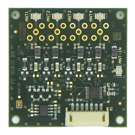
The module can be connected with the ID CPR74 reader by using the multi-pin connector X1. The following figure 4 and the corresponding table 2 show the pin assignment of the con- nector X1 (7-pole) of type “JST PH” spacing 2 mm (horizontal). Figure 3: „JST PH“ connector Figure 4: ID CPR.ANT.MUX.M4 Abbreviation Name Pin-No. - Page 8 Identification Installation ID CPR.ANT.MUX.M4 NOTE: The reader has to supplied by a limited power supply (e.g. NEC Class 2/LPS power sup- ply) according EN 62368-1 chapter Q.1, only Use only regulated power supply’s. The connection cable (VCC; IN1/2) should be as short as possible and must not exceed 3 m to reduce the influence of noise.
-
Page 9: Wiring
ID ISC.ANT100/100-U.FL-A Interface Connection cable ANT4 ANT3 5 VDC /GND 2 Control Wire ANT2 HF-Output - ANT1 Figure 5: Connection overview Figure 6: Connection cable between the ID CPR.ANT.MUX.M4 and the ID CPR74 FEIG ELECTRONIC GmbH Page 9 of 14 M70210-0e-ID-B.docx... -
Page 10: Reader Connection Ant-In
Identification Installation ID CPR.ANT.MUX.M4 4.3. Reader connection ANT-IN The antenna output of the reader will be connected with the input (ANT-IN) of the multiplexer by using a short U.FL cable. Figure 7: Position of the reader connector ANT-IN FEIG ELECTRONIC GmbH Page 10 of 14 M70210-0e-ID-B.docx... -
Page 11: Antenna Connection Ant1 - Ant4
Identification Installation ID CPR.ANT.MUX.M4 4.4. Antenna connection ANT1 – ANT4 The external antennas can be connected with the antenna connectors (ANT1...ANT4) with the help of an U.FL cable. Figure 8: Position of the antenna connectors ANT1 – ANT4 NOTE: ... -
Page 12: Indicators / Led
Identification Installation ID CPR.ANT.MUX.M4 5. Indicators / LED Each antenna output has a LED which shows the active antenna output channel. Only one channel will be active at the same time. Figure 9: Position of the LED FEIG ELECTRONIC GmbH Page 12 of 14 M70210-0e-ID-B.docx... -
Page 13: Technical Data
Identification Installation ID CPR.ANT.MUX.M4 6. Technical Data Table 3: Technical Data ID CPR.ANT.MUX.M4 Weight approx. 12g Operating -25 °C up to +70 °C (-13 °F up to +158 °F) Temperature Range Storage -40 °C up to +85 °C (-40 °F up to +185 °F) Humidity max. -
Page 14: Approvals
ID CPR.ANT.MUX.M4 7. Approvals 7.1. Europe (CE) Hereby, FEIG ELECTRONIC GmbH declares that the radio equipment type ID CPR.ANT.MUX.M4 is in compliance with Directive 2014/53/EU. The full text of the EU declaration of conformity is available at the following internet address: http://www.feig.de/en/downloads-support/declarations-of-conformity.html...
Need help?
Do you have a question about the ID CPR.ANT.MUX.M4 and is the answer not in the manual?
Questions and answers