
Subscribe to Our Youtube Channel
Related Manuals for Feig Electronic ISC.ANT.UMUX


Summary of Contents for Feig Electronic ISC.ANT.UMUX
- Page 1 INSTALLATION ID ISC.ANT.UMUX 8-times UHF Antenna Multiplexer final – public (B) 2013-02-07 – M71100-3e-ID-B.docx...
- Page 2 FEIG ELECTRONIC call explicit attention that devices which are subject of this document are not designed with components and testing methods for a level of reliability suitable for use in or in connection with surgical implants or as critical components in any life support systems whose failure to perform can reasonably be expected to cause significant injury to a human.
- Page 3 ® OBID i-scan Installation ID ISC.ANT.UMUX General information's regarding this document • The sign "" indicates extensions or changes of this manual compared with the former issue. • If bits within one byte are filled with "-", these bit spaces are reserved for future extensions or for internal testing- and manufacturing-functions.
-
Page 4: Table Of Contents
ID ISC.ANT.UMUX Contents 1. Safety Instructions / Warning - Read before start-up ! 2. Performance Features oft he ID ISC.ANT.UMUX 8 times UHF Antenna Multiplexer 7 2.1. Performance Features ....................... 7 2.2. Scope of Delivery ......................7 2.3. Available Multiplexer Types ....................7 3. - Page 5 ® OBID i-scan Installation ID ISC.ANT.UMUX ANNEX ANNEX A - Accessories ......................18 ANNEX A1 – Wall Mount Kit ID ISC.MS.MR/PR-A ............... 19 FEIG ELECTRONIC GmbH Page 5 of 19 M71100-3e-ID-B.docx...
- Page 6 ® OBID i-scan Installation ID ISC.ANT.UMUX 1. Safety Instructions / Warning - Read before start-up ! • The device may only be used for the intended purpose designed by for the manufacturer. • The operation manual should be conveniently kept available at all times for each user.
-
Page 7: Performance Features Oft He Id Isc.ant.umux 8 Times Uhf Antenna Multiplexer
The ID ISC.ANT.UMUX 8x UHF antenna multiplexer is designed for switching RFID antennas hav- ing an operating frequency of 860 MHz – 960 MHz. An ID ISC.ANT.UMUX allows multiple individ- ual antennas to be operated with just a single reader antenna output. -
Page 8: Wiring And Installation
® OBID i-scan Installation ID ISC.ANT.UMUX 3. Wiring and Installation 3.1. Dimensions The antenna multiplexer is designed for an indoor environment. It can be wall-mounted, in this case the wall mounting kit should be ordered separately. (see ANNEX A - Accessories and ANNEX A1 –... -
Page 9: Terminals And Jacks
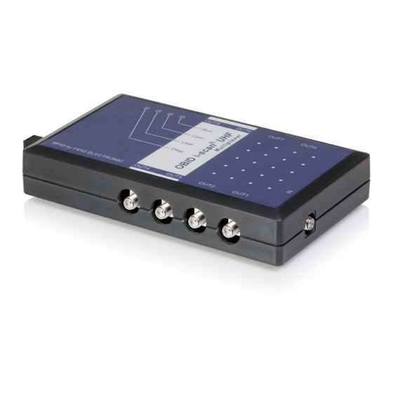
® OBID i-scan Installation ID ISC.ANT.UMUX 3.2. Terminals and Jacks Figure 2 shows the terminals, jacks, DIP switches and LED indicators. OUT8 OUT7 OUT6 OUT5 OUT1 OUT2 OUT3 OUT4 Figure 2: Terminals, jacks and operating elements 3.2.1. Supply Voltage The supply voltage is connected to X1 or directly to the Reader Connection IN. Configure the po- larity for X1 as shown in Figure 2. -
Page 10: Reader Connection - In
X1 as it is done in the normal operation mode. See also 3.2.1. Supply Voltage Figure 3: Connection of the Update Cable The procedure of the firmware update is described in Application Note ID ISC.ANT.UMUX – Firm- ware Update (N80301-xe-ID-B). -
Page 11: Operating And Display Elements
® OBID i-scan Installation ID ISC.ANT.UMUX 4. Operating and Display Elements 4.1. LEDs The LEDs, located on the SMA jacks OUT1-8, indicate which antenna connection is switched through. Table 2 shows the configuration of LEDs V1-4. Table 2: LED configuration... -
Page 12: Dip Switch S1
® OBID i-scan Installation ID ISC.ANT.UMUX 4.3. DIP Switch S1 4.3.1. Hardware Address setting DIP switches 1 and 2 are used for setting the hardware address. Table 3 summarizes the settings for the levels. Table 3: Address setting DIP switch S1... -
Page 13: Troubleshooting
® OBID i-scan Installation ID ISC.ANT.UMUX 5. Troubleshooting Error conditions that could appear at the multiplexer and their clear conditions are summarized in table 5. Table 5: Error Conditions Error Condition Error Trouble Shooting No function Interruption of the power supply... -
Page 14: Technical Data
® OBID i-scan Installation ID ISC.ANT.UMUX 6. Technical Data MECHANICAL DATA Housing Plastic, ABS Dimension (W x H x D) 85 mm x 145 mm x 27 mm 3.35 inch x 4.72 inch x 1.77 inch Weight 170 g (0.37 lbs) - Page 15 ® OBID i-scan Installation ID ISC.ANT.UMUX AMBIENT CONDITIONS Temperature Range • Operation -25 °C to +55 °C / -13 °F to + 131 °F • Storage -25 °C to +85 °C / -13 °F to + 185 °F Humidity 5 % to 95 % non-condensing...
-
Page 16: Radio Approvals
® OBID i-scan Installation ID ISC.ANT.UMUX 7. Radio Approvals 7.1. Europe (CE) When properly used this radio equipment conforms to the essential requirements of Article 3 and the other relevant provisions of the R&TTE Directive 1999/5/EC of March 99. Performance Classification according to ETSI EN 301 489: Class 2... -
Page 17: Declaration Of Conformity (Directive 1999/5/Ec - R&Tte)
® OBID i-scan Installation ID ISC.ANT.UMUX 7.2. Declaration of Conformity (Directive 1999/5/EC - R&TTE) Figure 4: Declaration of Conformity FEIG ELECTRONIC GmbH Page 17 of 19 M71100-3e-ID-B.docx... - Page 18 ® OBID i-scan Installation ID ISC.ANT.UMUX ANNEX ANNEX A - Accessories The following accessories are available for the multiplexer: Table 6: Accessories Article No. Part No. Description 2557.000.00 ID NET.24V-B 24 V DC/ power supply with suitable connector; Input voltage 100 - 240V AC 1691.000.01...
- Page 19 ® OBID i-scan Installation ID ISC.ANT.UMUX ANNEX A1 – Wall Mount Kit ID ISC.MS.MR/PR-A The wall mounting kit can be used to attach the Multiplexer to a flat surface. • Remove the screws from the back side of the Multiplexer.
Need help?
Do you have a question about the ISC.ANT.UMUX and is the answer not in the manual?
Questions and answers