Table of Contents
Advertisement
Quick Links
OWNERS MANUAL
www.herkules.us
Website:
info@herkules.us
E-mail:
This manual contains important information concerning the
installation and operation of the gun washers listed above.
Read manual thoroughly and keep for future reference
INSTRUCTIONS
Herkules Equipment Corporation
2760 Ridgeway Court
Walled Lake, MI 48390-1662 USA
Page 1 of 20
Part# 1002733-04
Made in USA
800-444-4351
Toll Free:
248-960-7100
Phone:
248 960-7109
Fax:
10/14/2020
Advertisement
Table of Contents

Subscribe to Our Youtube Channel
Related Manuals for Hercules G210


Summary of Contents for Hercules G210
- Page 1 Part# 1002733-04 10/14/2020 Made in USA This manual contains important information concerning the installation and operation of the gun washers listed above. OWNERS MANUAL Read manual thoroughly and keep for future reference INSTRUCTIONS Herkules Equipment Corporation 800-444-4351 www.herkules.us Toll Free: Website: 2760 Ridgeway Court 248-960-7100...
-
Page 2: Table Of Contents
Troubleshooting ……………………………………………………………………………………………………………… 13 Drawings with Part Lists …………………………………………………………………………………………………… 14 - 19 G210 Schematic ………………………………………………………………………………………………………....20 Herkules Equipment Corporation A U.S.-based manufacturer, Herkules Equipment Corporation offers a diverse line of products that support multiple industries by improving efficiency, productivity, ergonomics, comfort, and safety in the work environment. The company consists of the three product lines: Herkules, Enkon and BossLifts. -
Page 3: Warranty
Warranty IMPORTANT NOTICE: if you have a problem with your Herkules product, DO NOT RETURN TO PLACE OF PURCHASE Contact Herkules: by phone 1-800-444-4351; by email, info@herkules.us; or on the web at herkules.us/contact-us. At Herkules we take great pride in the construction of our American-made products, and we stand behind their reliability. Our limited liability warranty coverage for Paint Gun Washers warranties the unit for a period of 12 months. -
Page 4: Model Information
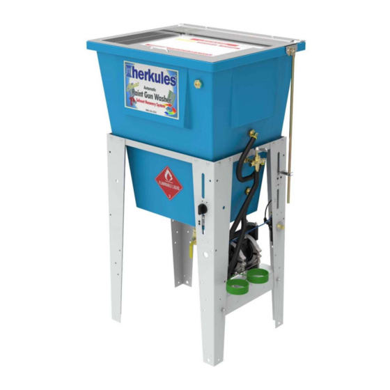
Weight Dimensions in./(mm) lbs/(kg) Two gun, two cup paint gun washer equipped with diaphragm 20.625 25.5 21.25 G210 pump, filter-regulator and timer. Adapted for pressure feed (1168) (524) (648) (540) (31) systems, paint hoses, and cans up to 5 gallons. -
Page 5: Warnings
WARNING EQUIPMENT MISUSE HAZARD Equipment misuse can cause the equipment to rupture, malfunction, or start unexpectedly and result in serious injury. • This equipment is for professional use only. • Read all instruction manuals, tags, and labels before operating the equipment. •... - Page 6 WARNING FIRE AND EXPLOSION HAZARD Improper grounding, poor air ventilation, open flames, or sparks can cause a hazardous condition and result in fire or explosion and serious injury. • Ground the equipment. See Installation for grounding procedure. • Provide fresh air ventilation to avoid the build up of flammable fumes from the cleaning solution. •...
-
Page 7: Assembly Instructions
Assembly Instructions Stand and tub connections STEP 1 Position the pump mount bracket between the timer leg and the filter/regulator leg of the stand assembly. Attach the pump mount bracket to the stand using (2) 1/4-20 x 1/2 hex bolts, (2) #10 flat washers, (2) 1/4" lock washers and (2) 1/4"... - Page 8 Assembly Instructions Connecting fluid and air hoses STEP 6 Insert the nipple and bushing end of the 3-way valve Limit valve 20" Fluid assembly into the upper bulkhead in the tub. Use sealant tube to avoid leaking and orient as shown [see fig.4]. STEP 7 Connect the 13"...
-
Page 9: Installation
Installation Installing the Gun Washer Place gun washer on a level surface in a properly ventilated paint mixing room or paint booth. Air supply port Grounding the Gun Washer Connect the ground wire on the gun washer’s pump to a true earth ground. - Page 10 Air Cap fig. 8 Assembly Trigger Lock Pressure Feed Gun Gravity Feed Gun (HVLP) Long Stem Support Short Stem Support Siphon Feed Gun Operating the Gun Washer Make sure all wire trigger locks and other accessories If the lid is opened prior to the end of the timing cycle, the are inside the gun washer tub.
- Page 11 Internal and External Washing of Paint Lines If necessary, install a female fluid quick coupler with 1/4" NPT male threads into the internal/external wash bulkhead located Paint line inside the tub, on the valve side of the tub [see fig.10]. Connect the paint line to the internal/external wash bulkhead.
-
Page 12: Preventative Maintenance
Preventative Maintenance To keep your machine working efficiently, please follow these directions. ALWAYS drain excess paint from cup or pot before placing in gun washer. Drain paint sludge from gun washer tank weekly. Do this after a weekend so that it has settled. Open ball valve and drain until clear solution flows. -
Page 13: Troubleshooting
Troubleshooting Problem Possible Solution Gun washer will not turn on. Make sure the air line is properly connected with at least 75 psi. Air pressure is regulated at 75 psi. Make sure lid is fully closed. Make sure the lid rod actuator is making full contact with the limit valve on the right rear leg. -
Page 14: Drawings With Part Lists
G210 Parts Layout Page 14 of 20... - Page 15 G210 Parts Layout Part # Description Quantity Ball Valve 1 EA. 11958 Pump Mounting Bracket 1 EA. 13844 Stand Assembly 1 EA. 12025 Lid Assembly 1 EA. 12734 Manifold Assembly 1 EA. 12517 Pump Assembly 1 EA. 1000651 Flammable Caution Sticker 1 EA.
- Page 16 G210 Lid Layout Part # Description Quantity 002-161 Washer Flat #10 USS - Zinc 8 EA. 1000252 Actuator Clip Ring 1 EA. 1000652 Actuator Pin 1 EA. 1001708 Lid Sticker 1 EA. 1002546 Screw 10-24 x 1/2 4 EA. 1002572 Actuator Rod 1 EA.
- Page 17 G210 Manifold Layout Part # Description Quantity Hose Barb 3/8 x 1/4 NPT - Brass 1 EA. Hex Plug 1/8 NPT - Brass 3 EA. 12509 Air Cap Assembly - Brass and Stainless 2 EA. 12599 Spray Nozzle Assembly 1 EA.
- Page 18 G210 Pump and Legs Layout Page 18 of 20...
- Page 19 G210 Pump and Legs Layout Part # Description Quantity Adaptor 1/4 NPT - Brass 1 EA. 12517 Pump Assembly 1 EA. 1001441 Muffler 1 EA 13844 Stand Assembly 2 EA. Bolt Hex Full 1/4-20 x 1 GD5 Z 2 EA.
-
Page 20: G210 Schematic
G210 Schematic Page 20 of 20...
Need help?
Do you have a question about the G210 and is the answer not in the manual?
Questions and answers