Table of Contents
Advertisement
Advertisement
Table of Contents

Related Manuals for Demco 650


Summary of Contents for Demco 650
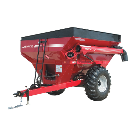
- Page 1 AG20016, Rev 19 11/20 GRAIN CART 650-750 BUSHEL...
-
Page 2: Warranty Policy & Registration
INTRODUCTION Thank you for purchasing a Demco Grain Cart. We feel you have made a wise choice and hope you are completely satisfied with your new piece of equipment. Proper care and use will result in many years of service. -
Page 3: Table Of Contents
Adjustable Discharge Chute Option Parts Breakdown ............16 Grain Cart Assembly and Parts Breakdown ................ 17-18 650 Bushel Extensions Assembly and Parts Breakdown ............. 19 750 Bushel Extensions Assembly and Parts Breakdown ............. 20 Hydraulics Assembly and Parts Breakdown ................21 Optional Hydraulic Block Schematic .................. -
Page 4: Safety, Signal Words
If you have questions not answered in this manual, require additional copies, or if your manual is damaged, please contact your dealer or Demco, 4010 320th Street, Boyden, IA 51234 ph: (712) 725-2311 or Toll Free: 1-800-543-3626 Fax: (712) 725-2380 http://www.demco-products.com... -
Page 5: Equipment Safety Guidelines, Lighting And Marking
SAFETY sAfeTy...you cAN lIve WITh IT EqUIPMENT SAFETY GUIDELINES Every year many accidents occur which could have been avoided by a few seconds of thought and a more careful approach to handling equipment. You, the operator, can avoid many accidents by observing the following precautions in this section. -
Page 6: Safety Sign Care, Tire Safety
• NeveR exceed 40 psi tire inflation when using truck tires on gravity flow wagons. • Refer to “TIRe INflATIoN chART” in your owners manual for maximum tire pressure for a Demco Grain Cart. -
Page 7: Before Operation
SAFETY BEFORE OPERATION: • Carefully study and understand this manual and the Owner’s Manual. • Do not wear loose-fitting clothing which may catch in moving parts. • Always wear protective clothing and substantial shoes. • It is recommended that suitable protective hearing and eye protection be worn. • Operator may come in contact with certain materials which may require specific safety equipment relative to handling of such materials. (Examples: extremely dusty, molds, fungus, bulk fertilizers, etc.) • Keep wheel and lug nuts tightened to specified torque. • Assure that agricultural implement tires are inflated evenly. • Give unit a visual inspection for any loose bolts, worn parts, or cracked welds, and make necessary repairs. Follow maintenance safety instructions included in this manual. • Be sure there are no tools lying on or in equipment • Do not use unit until you are sure that area is clear, especially around children and animals. -
Page 8: Following Operation
SAFETY • When halting operation, even periodically, set tractor or towing vehicles brakes, disengage PTO, shut off engine, and remove ignition key. • Be especially observant of operating area and terrain. Watch for holes, rocks, or other hidden hazards. Always inspect area prior to operation. DO NOT operate near edge of drop-off or banks. DO NOT operate on steep slopes as overturn may result. Operate up and down (not across) intermediate slopes. Avoid sudden starts and stops. • Pick the most level possible route when transporting across fields. Avoid edges of ditches, gullies, and steep hillsides. -
Page 9: Highway And Transport Operations
SAFETY HIGHWAY AND TRANSPORT OPERATIONS • sAfeTy chAINs: If equipment is going to be transported on a public highway, always follow state and local regulations regarding safety chains and auxiliary lighting. Be sure to check with local law enforcement agencies for your own particular regulations. Only safety chains (not elastic or nylon/plastic tow straps) should be used to retain connection between towing and towed machines in event of separation of primary attaching system. Use a high strength, appropriately sized hitch pin with a mechanical retainer and attach safety chains. -
Page 10: Performing Maintenance
SAFETY PERFORMING MAINTENANCE • Good maintenance is your responsibility. Poor maintenance is an invitation to trouble. • Make sure there is plenty of ventilation. Never operate engine of towing vehicle in a closed building. Exhaust fumes may cause asphyxiation. • Before working on this machine, stop towing vehicle, set brakes, shut off engine and remove ignition key. • Always use safety support and block wheels. Never use a jack to support machine. • Always use proper tools or equipment for job at hand. • Use extreme caution when making adjustments. • Follow torque chart in owners manual when tightening bolts and nuts. • Never use your hands to locate a hydraulic leak on attachments. Use a small piece of cardboard or wood. Hydraulic fluid escaping under pressure can penetrate skin. •... -
Page 11: Safety Sign Locations
SAFETY SAFETY SIGN LOCATIONS Types of safety sign and locations on equipment are shown in illustration below. Good safety requires that you familiarize yourself with various safety signs, type of warning, and area or particular function related to that area, that requires your SAFETY AWARENESS. #1 DANGER - Do not enter grain tank when auger is running! #2 DANGER - Keep off ladder while machine is being moved or in operation! - Page 12 SAFETY SAFETY SIGN LOCATIONS Types of safety sign and locations on equipment are shown in illustration below. Good safety requires that you familiarize yourself with various safety signs, type of warning, and area or par- ticular function related to that area, that requires your SAFETY AWARENESS. decal order number AG21064 DANGER - This decal is on pto shaft, Guard is missing do not operate! #10 DANGER -...
-
Page 13: Bolt Torque
BOLT TORqUE TORqUE SPECIFICATION Torque figures indicated are valid for non-greased or non-oiled threads and heads unless otherwise specified. Therefore, do not grease or oil bolts or capscrews unless otherwise specified in this manual. When using locking elements, increase torque values by 5%. * GRADE or CLASS value for bolts and capscrews are identified by their head markings. -
Page 14: Axle Assembly And Parts Breakdown
AXLE ASSEMBLY NoTe: for carts equipped with a scale, see page 24 for spe- cial seal 650, & 750 with the scale option uses 2 Washers (item # 11) NoTe: 10, 11, and 12 are not included with a replacement hub Ref. -
Page 15: Auger Assembly And Parts Breakdown
REPLACEMENT PARTS AUGER ASSEMBLY 50 51 Ref. PART QTy. descRIPTIoN 21. 09195-30 Hanger Bearing Mount 22. 09196-30 Hanger Bearing Plate 07412 1-1/4”-12 UNF Jam Nut 00085 1/2” Flatwasher 02178 1/2”-13 UNC Nylon Inset Locknut 26. 12233-30 Male Cast Auger Connection 27. 09199-30 Gauge Rod 28. 11771-30 Inner Door 29. 03738-95 1” Dia. x 3” Cylinder Pin 00116 5/32”... -
Page 16: Adjustable Discharge Chute Option Parts Breakdown
Seal, End Cap 13973 Plug, 1/2” 13974 Plug, 1/4” 13975 Plug, 1/8”, Vent 14777 Gamma Seal deMco Replacement Parts for Gearbox # 07924 Please order replacement parts by PART No. and descRIPTIoN. SEE SEPARATE BILL OF MATERIAL Page 16 AG20016 DFTR DATE... -
Page 17: Grain Cart Assembly And Parts Breakdown
REPLACEMENT PARTS GRAIN CART PARTS BREAkDOWN for extension breakdown see Page 19 and 20 for Auger breakdown see Page 15 for Window Installation see Page 27 for hydraulic drive option see Page 26 for PTo breakdown see Page 25 for door lift breakdown see Page 27 for Axle breakdown see Page 14... - Page 18 • Never fill grain cart unless inner gate is closed. 51. 12468-30 SMV Sign Bracket 07594 3/8” x 1” Self Tapping Bolts • Never engage auger when system is moving at a 53. 09380-60 32” x 21” Rim (650/750) high rate of speed. 09381-60 32” x 27” Rim (650/750) T24.5l 24.5” x 32” x 12 Ply Tire • Never do maintenance work or service cart while the T30.5d...
-
Page 19: 650 Bushel Extensions Assembly And Parts Breakdown
REPLACEMENT PARTS 650 BUSHEL EXTENSION ASSEMBLY Ref. PART QTy. descRIPTIoN 11124-30 Left Extension 11126-30 Rear Extension 11123-30 Right Extension 11125-30 Front Extension 11180-30 Extension Cross Brace 01263 54 5/16”-16 UNC x 3/4” Hex Head Bolt (Gr.5) 02802 66 5/16”-16 UNC Nylon Insert Locknut 00004 38 5/16” Flat Washer 13154-30 Extension Hinge Middle 10. 13153-30 Extension Hinge Side 11. -
Page 20: 750 Bushel Extensions Assembly And Parts Breakdown
REPLACEMENT PARTS 750 BUSHEL EXTENSION ASSEMBLY Ref. PART QTy. descRIPTIoN 11128-30 Left Extension 11130-30 Rear Extension 11127-30 Right Extension 11129-30 Front Extension 11180-30 Extension Cross Brace 00059 3/8” Flat Washer 02592 11 3/8”-16 UNC Nylon Insert Locknut 13052 3/8” UNC X 1.25 Slotted Truss Head Bolt 01263 54 5/16” -16 UNC x 3/4” Hex Head Bolt (Gr. 5) 00004 5/16” Flatwasher 02802 66 5/16” -16 UNC Nylon Insert Locknut 12. -
Page 21: Hydraulics Assembly And Parts Breakdown
REPLACEMENT PARTS HYDRAULICS PARTS AND ASSEMBLY (shown with optional Adjustable hydraulic discharge chute) for optional Pendant/ hydraulic block schematic, see Page 22 Item #8 is on opposite side of fittings inside box Ref. PART Ref. PART QTy. descRIPTIoN QTy. descRIPTIoN 05198 Rubber Coupler Cover (Black) 11. -
Page 22: Optional Hydraulic Block Schematic
REPLACEMENT PARTS OPTIONAL PENDANT CONTROL HYDRAULIC SCHEMATIC Ref. PART Ref. PART QTy. descRIPTIoN QTy. descRIPTIoN 13882 13891 Replacement O-Ring 3/8” MPT x #6 JIC Elbow W/ .041 Orifice 13886 05190 1/4” x 48” Hydraulic Hose 90° Elbow Hyd. Fitting w/ O-Ring w/ .41 Orifice 05191 1/4” x 36” Hydraulic Hose 12374 Bulkhead Hydraulic Fitting, 45° 05195 Str. Hyd. Fitting, .375 MPT 13884 1/4” x 420” Hydraulic Hose 13890 13885 1/2” x 16’ Hydraulic Hose... -
Page 23: Lighting Assembly And Parts Breakdown
REPLACEMENT PARTS LIGHTING PARTS AND ASSEMBLY (left) yellow band Ref. PART QTy. descRIPTIoN Amber 03652 Grommet Rubber Oval Turn/flasher To Auger light 14923 LED Light, Sealed Red Lamp 14924 LED Light, Sealed Yellow Lamp 07416 7-Way Male Plug Connector 09149 Wiring Harness 14981 Chute Light Wire Harness Please order replacement parts by PART No. -
Page 24: Scale Option And Parts Breakdown
Parts breakdown of all other hub and axle parts see page 14. Ref. PART QTy. descRIPTIoN 09410 Spindle Insert (650-750 Bu.) 12260 Spindle w/ 21’ Wire Harness (650-750 Bu.) 09442 Grease Seal (650-750 Bu.) 09414-95 Rear Hitch Scale Pin 09411 Hitch Insert 12262 Hitch Scale w/ 10’ Wire Harness... -
Page 25: Pto Drive Shaft Breakdown
REPLACEMENT PARTS PTO DRIVE SHAFT PARTS BREAkDOWN check the PTo overlap length. Try to obtain the greatest possible overlap without bottoming out the PTO shaft in its maximum operating condition. Make sure draw bar length and PTO telescoping limits are adequate for uneven terrain, gullies, levees, etc. Ref. -
Page 26: Hydraulic Drive Assembly And Parts Breakdown
REPLACEMENT PARTS HYDRAULIC DRIVE ASSEMBLY *NoTe: hydraulic motor has a capacity of 15-25 gallons per minute. for opti- mum motor speed, 25 GPM and return line should be connected directly to the low pressure return port. 13,16* Ref. PART QTy. descRIPTIoN 05198 Rubber Coupler Cover... -
Page 27: Window Assembly And Door Lift Assembly Breakdown
REPLACEMENT PARTS WINDOW INSTALLATION Locking Tab in Closed Position Window Gravity Box INsTAllATIoN PRoceduRe Inside of Box The installation must be done from inside the Locking Tab box. 1. Place rubber molding in opening. Seam should begin on side of opening. 2. -
Page 28: Grease And Lube Instructions
MAINTENANCE GREASE & LUBE Reference numbers Are u-joints -- check and grease regularly. Reference number - Is a Telescoping P.T.o. shaft with two slots in housing -- fully extend P.T.o. shaft, then place one or two pumps of grease in each slot. Reference numbers Are fixed self centering sealed bearings -- do not over grease sealed bearings. -
Page 29: Inner Door Maintenance, Gear Box Lube Instructions
MAINTENANCE INNER DOOR MAINTENANCE / LUBE INSTRUCTIONS Ref. PART QTy. descRIPTIoN 04642 1/4” Self Tapping Grease Zerk 11771-30 Inner Door 09203 Slide Rod Please order replacement parts by PART No. and descRIPTIoN. 1. Run the inner door (#2) fully open and disconnect hydraulic lines to the grain cart. -
Page 30: Grain Cart Checklist
MAINTENANCE GRAIN CART CHECkLIST: downtime in the fields caused by field breakdowns is costly and time consuming. Many breakdowns can be eliminated by periodic equipment maintenance. by spending a little time running over this checklist, following proper after-season care, you can save time and money later on. WARNING: To Prevent serious Injury or death •... -
Page 31: Tire Inflation
MAINTENANCE Tire Inflation Chart GRAIN CART APPLICATION TIRE SIZE P LY M AXIMUM TIRE PSI. 650-750 Bushel Lug Tire 24.5 x 32 32 psi. 650-750 Bushel Diamond Tire 24.5 x 32 32 psi. 650-750 Bushel Lug Tire 30.5 x 32 26 psi. 650-750 Bushel Diamond Tire 30.5 x 32...
Need help?
Do you have a question about the 650 and is the answer not in the manual?
Questions and answers