
Subscribe to Our Youtube Channel
Related Manuals for Honeywell T610


Summary of Contents for Honeywell T610
- Page 1 T610 Honeywell Server Planning, Installation, and Service Guide EP-DPCX15-en-F August 2020...
- Page 2 Honeywell International Sàrl. While this information is presented in good faith and believed to be accurate, Honeywell disclaims the implied warranties of merchantability and fitness for a purpose and makes no express warranties except as may be stated in its written agreement with and for its customer.
-
Page 3: Table Of Contents
2.2 Description 2.2.1 Honeywell server model number 2.2.2 Equipment configuration 2.2.3 Electronics module 2.2.4 Storage and media devices 2.2.5 Standard features of Dell PowerEdge T610 server server 2.2.6 Slots configuration 2.2.7 Optional features 2.2.8 Power cords 2.3 Platform information 2.3.1 Honeywell documentation 2.3.2 Dell documentation... - Page 4 3.4.4 Install air duct baffles and blank panel front covers in cabinet 3.5 Starting the server 3.5.1 To start the server 3.5.2 Configuring RAID in Dell PowerEdge T610 server 3.5.3 Starting the TDC emulator services 3.5.4 Checking the LCNP4e/LCNp4e2 status...
- Page 5 Chapter 4 - Operation 4.1 Server overview 4.1.1 Front view of Dell PowerEdge T610 server 4.1.2 Rear view of Dell PowerEdge T610 server 4.2 Network connections 4.2.1 Ethernet network 4.2.2 LCN network 4.2.3 LCN cables 4.2.4 LCN connections 4.2.5 MAU connection 4.2.6 ControlNet Network...
-
Page 6: Chapter 1 - About This Guide
CHAPTER BOUT THIS GUIDE This document contains installation and service information for the Dell PowerEdge T610 server. The instructions and service information contained herein address the server itself, and assumes that associated network communication equipment has been pre-installed by the Honeywell factory or has manuals dedicated to its installation and service. -
Page 7: Chapter 2 - Planning
Light industrial regulatory compliance Overview Platforms sold by Honeywell are engineered for the process control mission of Experion and TPS systems to provide consistent and robust performance. Through an extensive qualification process, Honeywell defines specific peripheral devices, slot locations, and BIOS settings for best performance and reliability, sometimes even adding cooling fans for longer service. -
Page 8: Bios Configuration
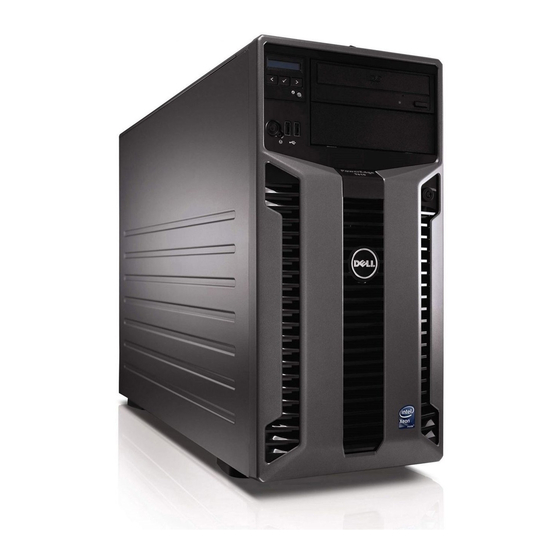
T610 Honeywell server (Rack Mount) 51154292-200 MZ-PCSV23 T610 Honeywell MLK server (Tower Unit) 51154292-300 MZ-PCSV33 T610 Honeywell MLKserver (Rack Mount) 51154292-400 The following illustrates the front view of a Dell PowerEdge T610 server (MZ-PCSV32 and MZ-PCSV33) Rack Mount platform. - 8 -... -
Page 9: Equipment Configuration
2.2.2 Equipment configuration The Dell PowerEdge T610 server server is used for TPS and Experion nodes and must be rack mounted only on a 1-meter deep Honeywell equipment cabinet, with model number MP-C1MCB1. Server model number MZ-PCSV22 is a tower unit. When mounted in a cabinet, the enclosure uses 5U of space. -
Page 10: Storage And Media Devices
2.2.5 Standard features of Dell PowerEdge T610 server server The following is a list of the common features of Dell PowerEdge T610 server. Dell motherboard with Single Intel® Xeon® X5560, 2.8Ghz, 8M Cache, Turbo, HT, 1333MHz Max Memory 6.4GT/s QPI. (For Model 51154292-100 and 51154292-200 only). -
Page 11: Slots Configuration
Chapter 2 - Planning Five PCIE Generation Two full-height Full-length x8 link (slot two and three) Three full-height, half-length x4 link (slot one, four and five) Energy Smart – Two hot-plug high-efficient 570W Power Supply. Two 110 Volt / 230Volts Power Cords. 2x2GB 1R low voltage UDIMM DDR3 1067MHz Adv. -
Page 12: Power Cords
AC power cord, 110 V Use Dell power cord supplied with server AC power cord, 220 V (2) 5130557-100 The following table lists the Honeywell AC power cords (factory installed) for cabinet rack mount configuration. Part description Part number AC power cord, 120 V... - Page 13 Chapter 2 - Planning Publication Contains information on Available Information Update Last-minute updates about technical Packaged with changes to your computer or advanced the computer. technical-reference material for experienced users or technicians. Dell™ PowerEdge™ Warranty and Safety. Packaged with Product Information the computer.
-
Page 14: Slot Requirements For Tpn Node Setup
Chapter 2 - Planning Slot requirements for TPN node setup The following table identifies the specific slots for the Honeywell options for a TPN node configuration. Slot number Slot type Description PCI-E x4 Free slot PCI-E x8 Free slot PCI-E x8... -
Page 15: General Ethernet Slot Requirements
Chapter 2 - Planning General Ethernet slot requirements General Ethernet must be used on the first/second on-board NICs. 2.6.1 Option 1 – Single NIC (One On-board NIC) Slot number Slot type Description PCI-E x4 Free slot PCI-E x8 Free slot PCI-E x8 Free slot PCI-E x4... -
Page 16: Option 4 - 4 Nics (Dual Nic With Two On-Board Nics)
Device options In addition to the standard configuration for the server, your platform can be configured with additional options based on the model number you ordered. The following table lists optional items for Dell PowerEdge T610 server. Model number Description... - Page 17 Chapter 2 - Planning Standard and optional memory configuration for model 51154292-100 and 51154292-200 only DIMM 2 GB Memory Socket (standard) 4 GB Memory Not available for use Not available for use Not available for use Not available for use 1 GB 1 GB, 1066 MHz, 1R Adv ECC DDR3 UDIMM...
-
Page 18: Other Options
2.7.3 Other options Honeywell offers a cabinet mounted 8-port KVM switch/control console (model number TP-KVMCB1 for switch with PS/2 interface and model number TP-KVMCB2 for switch with USB interface) to provide a human interface (booting and maintenance activities) to cabinet mounted servers. Either option comes pre-installed from the Honeywell factory. -
Page 19: System Specifications
Chapter 2 - Planning System specifications 2.8.1 Environmental specifications for a tower unit Description Tower (Cannot mount on rack) Temperature 10∨dm; to 35∨dm; C (50∨dm; -95∨dm; F) Relative Humidity 20 to 80%, non-condensing Max Vibration 0.26 G at 10-350 Hz for 10 minutes Max Shock half shock pulse of 31 G for up to 2.6 ms Altitude... -
Page 20: Electronic Assembly Specifications
Chapter 2 - Planning 2.8.4 Electronic assembly specifications DC POWER AC Voltage 120 (90-132) Vrms 240 (180-260) Vrms AC RMS 2.45 Arms Current 1.34 Arms AC Power 294 Watts 323 Watts 2.8.5 Maximum Operating Power Requirements DC POWER AC Voltage 120 (90-132) Vrms 240 (180-260) Vrms AC RMS Current... -
Page 21: Hard Disk Drive Specifications
Hard disk drive specifications The Dell PowerEdge T610 server has five hard disk drives. It uses four 146 GB SAS 2.5” hard drives for RAID-5 (striping). The fifth hard drive is used as a hot spare drive. There is no option to add additional hard drives. -
Page 22: Keyboard
After connecting the keyboard, you must download the latest diagnostics from the Dell Support Website at http://www.support.dell.com/. Honeywell offers a cabinet mounted 8-port KVM switch/control console (model number TP-KVMCB1 for switch with PS/2 interface and model number TP-KVMCB2 for switch with USB interface) to a provide human interface (booting and maintenance activities) to cabinet mounted servers. -
Page 23: Safety Compliance
The compliance specifications in this section apply to installations other than cabinets. ATTENTION Honeywell does not claim Safety Compliance or Electromagnetic Compatibility (EMC) Compliance for system equipment configurations that have not been described in this guide as standard system configurations. Any equipment configuration other than that described in this publication decertifies the Safety and EMC compliance of this product. -
Page 24: Safety Compliance
Chapter 2 - Planning Regulatory) for European community. Element Description Emissions IEC 61326, 1997 (Basic Requirements, CISPR 11, Class A) Immunity IEC 61326, 1997 (Basic Requirements) ATTENTION The following formula is a proximity guideline, for use of Portable Transceivers (walkie-talkies) in the frequency range of 80MHz to 1GHz. -
Page 25: Chapter 3 - Installation
CHAPTER NSTALLATION This section describes the procedures for installing the platform and cabling the server in a 1-meter deep Honeywell cabinet. Tasks for installing the server Power and grounding requirements Cabinet spacing requirements Installing the server and connecting the cables... -
Page 26: Grounding Consoles And Cabinets
Uninterruptible Power Source (UPS). Cabinet spacing requirements Due to physical constraints, only one Dell PowerEdge T610 server can be mounted on a 1-meter deep Rittal MP-C1MCB1 cabinet from Honeywell. The server must be mounted on rack space interval 11U through 15U counting from the bottom of the cabinet and moving up. -
Page 27: Installing The Server And Connecting The Cables
This section describes the procedures for installing and cabling the server as a tower unit or in a 1- meter deep Honeywell cabinet. The human interface can access locally in the cabinet. This procedure assumes a new 1-meter deep equipment cabinet, Honeywell model number MP-C1MCB1, was shipped from the Honeywell factory with Versa Rail slides pre-assembled. -
Page 28: Installing The Server
To install the server 1. Connect the power cords and all cables to the back panel of the server. 2. Fully extend the right and left Versa Rail slides (pre-installed at the Honeywell factory) in the cabinet. 3. Lower the server into the J-shaped slots on each slide, starting with the slot closest to the cabinet. -
Page 29: Connecting The Cables
Failure to do so may result in tripping the circuit breakers. 2. Connect the Honeywell AC power cords. ATTENTION To ensure redundant power, the AC power cords from redundant power supplies must be connected to both sides of the redundant power entry. - Page 30 Chapter 3 - Installation To install air duct baffles and blank panel front covers in cabinet 1. Place the air duct baffle inside the cabinet with the bent tab resting along the front of the right cabinet rail. Figure 3.2 Installation of Air Duct Baffle and Blank Panel Front Cover - 30 -...
-
Page 31: Starting The Server
If the power light does not become solid green, refer to the troubleshooting section of the Dell™ PowerEdge™ R710 Systems Hardware Owner’s Manual . Configuring RAID in Dell PowerEdge T610 server Starting the TDC emulator services Checking the LCNP4e/LCNp4e2 status 3.5.2... - Page 32 While performing the following steps, you cannot access the information present in the hard drives. To configuring RAID in Dell PowerEdge T610 server 1. Turn on the server. 2. After starting the server, the following message appears.
-
Page 33: Starting The Tdc Emulator Services
LCNP4e/LCNp4e2 passed self test. To check the LCNP4e/LCNp4e2 status 1. Choose Start > Programs > Honeywell TPS > LCNP Status. 2. Verify that the LCNP status indicates Passed Self Test and the circle is green. -
Page 34: Chapter 4 - Operation
Rear view of Dell PowerEdge T610 server 4.1.1 Front view of Dell PowerEdge T610 server The following image illustrates the front view of the Dell PowerEdge T610 server. 4.1.2 Rear view of Dell PowerEdge T610 server The following image illustrates the rear view of the Dell PowerEdge T610 server. -
Page 35: Network Connections
The connection to the LCN is made through a Local Control Network Processor (LCNP4E) card. This card is a Honeywell card that allows the TPS Operator Station to emulate Universal Stations. This card provides the communication path for the server to other LCN modules. The LCNP4E consists of an LCNP4E card, a MAU cable, and the LCN MAU (Media Access Unit). -
Page 36: Lcn Cables
Chapter 4 - Operation The LCN node address must meet the customer requirements. If the LCN address is not known, the node address must be set to zero. Setting the address to zero allows the node to connect to the LCN without the risk of an address conflict with some other node. -
Page 37: Controlnet Network
The model number for the ControlNet Universal Interface is TC-PCIC02-100. Controlnet Network interface must be connected to T610 Honeywell Server using Magma PCIe to PCI converter box. For more information on how to connect, refer to the Magma PCI Expansion Chassis Installation Instructions (PE4DR-HNWL) supplied with the Magma hardware kit. -
Page 38: Removing Existing Pcie Riser
Chapter 4 - Operation Removing existing PCIe riser Installing PCIe riser card and ControlNet card 4.3.1 Removing existing PCIe riser PCIe riser is an electrostatically sensitive device. Use a grounding strap, grounded work surfaces and equipment when handling this component. To remove existing PCIe riser 1. -
Page 39: Installing Pcie Riser Card And Controlnet Card
Chapter 4 - Operation 5. Press the blue clip and lift gently to remove the riser card. The raiser card looks as displayed in the image. 6. Unscrew the riser card from bracket as displayed in the image. ATTENTION Ensure that you DO NOT connect the power cord. 4.3.2 Installing PCIe riser card and ControlNet card To Install PCIe riser card and ControlNet card... - Page 40 Chapter 4 - Operation 1. Insert PCIe riser card in the bracket as displayed in the image. 2. Tighten the screw as displayed in the image. The slot card along with bracket is ready for insertion into the server system. 3.
- Page 41 Chapter 4 - Operation 4. Insert PCIe based PCIC-02 ControlNet interface card in PCIe slot. 5. Close the card restrainer/clip which was removed earlier. - 41 -...
- Page 42 Chapter 4 - Operation 6. Close the cover of the server system and push the flip. 7. Insert the power chords back to the server. 8. Turn on the server. - 42 -...
-
Page 43: Chapter 5 - Servicing
ERVICING Remove the front bezel Remove the side cover Servicing the LCNP4e/LCNp4e2 Servicing the hard disk drives and power supply Servicing Honeywell options Verifying correct BIOS settings Troubleshooting Spare parts Remove the front bezel A lock on the bezel restricts access to the hard drives. To remove or install any of these drives, you must first remove the front bezel. -
Page 44: To Remove The Side Cover
Chapter 5 - Servicing components on the motherboard; you must first remove the side cover. 5.2.1 To remove the side cover 1. Turn the lock on the cover release latch counterclockwise to unlock position. 2. Press the release latch, and rotate the latch end of the cover away from the system. 3. -
Page 45: Replacing The Lcnp4E Board
Replacing the LCNP4E board The LCNP4E board is located in the PCIE slot 5. Refer to the following steps to replace the LCNP4E card. See also Dell™ PowerEdge™ T610 Systems Hardware Owner’s Manual. CAUTION The LCNP4E board is an electrostatically sensitive device. Use a grounding strap and grounded work surfaces and equipment when handling this component. -
Page 46: Servicing The Hard Disk Drives And Power Supply
15. Press the Power On/Off button on the server, to turn on the server. Servicing the hard disk drives and power supply The server from Honeywell is configured with 5, 146 GB SAS hard drives. Four are used in a RAID-5 - 46 -... -
Page 47: Servicing Honeywell Options
Refer to the Dell documentation listed in the following table for detailed instructions on swapping the power supply and hard disk drive. Publication Contains information on Dell™ PowerEdge™ T610 Systems System Overview Hardware Owner’s Manual Basic Troubleshooting Indicators, Codes, and Messages... -
Page 48: Slot Requirements For Tpn Node Setup
Chapter 5 - Servicing 5.5.1 Slot requirements for TPN node setup The following table identifies the specific slots for the Honeywell options for a TPN node configuration. Slot number Slot type Description PCI-E x4 Free slot PCI-E x8 Free slot... -
Page 49: Replacing The Cards In Expansion Slots
Replacing the cards in expansion slots The following procedure contains information on replacing the expansion cards in the PCIE slots. See also Dell™ PowerEdge™ T610 Systems Hardware Owner’s Manual. To replace the cards in expansion slots 1. Disconnect the cables from the expansion card. -
Page 50: Add Additional Memory
Chapter 5 - Servicing ATTENTION Keep this bracket in case you need to remove the expansion card later. Filler brackets must be installed over empty expansion card slots to maintain Federal Communications Commission (FCC) certification of the system. The brackets also keep dust and dirt out of the system and aid in proper cooling and airflow inside the system. - Page 51 Chapter 5 - Servicing To add additional memory 1. Remove the front bezel. Perform the steps in section Remove the front bezel. 2. Remove the side cover. Perform the steps in section Remove the side cover. 3. Press and hold the shroud release latch in the direction of the arrow. 4.
- Page 52 Chapter 5 - Servicing 6. While wearing a grounded ESD wrist strap, press the socket ejectors on the memory module socket down to allow the memory module to be inserted into the socket. 7. Insert the memory module as described in section Memory configuration.
-
Page 53: Verifying Correct Bios Settings
Chapter 5 - Servicing Verifying correct BIOS settings All Honeywell systems must have the Honeywell recommended BIOS version. Honeywell configures specific BIOS settings in the factory for each of the server platform configurations, and these settings must not be altered. BIOS settings for the server are listed in the tables. -
Page 54: Entering The Bios
Chapter 5 - Servicing 5.6.1 Entering the BIOS To enter the BIOS 1. Turn on the server. 2. Press F2 to enter the BIOS Setup. 3. Check if the BIOS version is 1.3.6 or later. 5.6.2 BIOS Settings for 51154292-100 and 51154292-200 The following sections lists the BIOS settings configured in the factory for the server platform. - Page 55 Chapter 5 - Servicing Item Value Logical Processor Enabled Virtualization Technology Disabled Adjacent Cache Line Prefetch Enabled Hardware prefetcher Enabled Execute Disable Enabled No. Of Cores/Processor Turbo Mode Enabled C-State Enabled C1 E state Enabled Processor 1 Family – Model – Stepping 06-1A-5 or higher Intel®...
- Page 56 Chapter 5 - Servicing Item Value Boot Sequence Retry Disabled Integrated devices Item Value Integrated RAID Controller Enabled User Accessible USB Ports All Ports ON Internal USB Port Internal SD Card Port Embedded NIC 1 and NIC 2 Enabled Embedded GB NIC 1 Enabled MAC Address Xxxxxxxxxxxx...
- Page 57 Chapter 5 - Servicing Item Value Embedded Video IRQ 10 Embedded SATA1 IRQ 14 Serial communication Item Value Serial Communication On without Console Redirection External Serial Connector COM1 Fail-Safe Baud Rate 115200 Remote Terminal Type VT100/VT220 Redirection After Boot Enabled Embedded server management Item Value...
-
Page 58: Bios Settings For 51154292-200 And 51154292-300
Chapter 5 - Servicing Item Value F1/F2 Prompt on Error Enabled 5.6.3 BIOS Settings for 51154292-200 and 51154292-300 The following sections lists the BIOS settings configured in the factory for the server platform. Your configuration may vary. System date and time Item Value System Time... - Page 59 Chapter 5 - Servicing Item Value Adjacent Cache Line Prefetch Enabled Hardware prefetcher Enabled DCU Streamer Prefetcher Enabled Data Reuse Enabled Execute Disable Enabled No. Of Cores/Processor Demand Based Power Management Disabled Turbo Mode Enabled C-State Enabled C1 E state Enabled Processor 1 Family –...
- Page 60 Chapter 5 - Servicing Item Value Hard drive C: Enabled Boot Sequence Retry Disabled Integrated devices Item Value Integrated RAID Controller Enabled User Accessible USB Ports All Ports ON Internal USB Port Internal SD Card Port Embedded NIC 1 and NIC 2 Enabled Embedded GB NIC 1 Enabled...
- Page 61 Chapter 5 - Servicing Item Value Embedded USB EHCI Controller 1 IRQ 6 Embedded Video IRQ 10 Embedded SATA1 IRQ 14 Serial communication Item Value Serial Communication On without Console Redirection Serial port address Serial Device 1 = Com1 Serial Device 2 = Com 2 External Serial Connector Serial Device 1 Fail-Safe Baud Rate...
-
Page 62: Troubleshooting
5.7.1 Integrated Dell Remote Access Controller 6 (iDRAC6) issue The Dell PowerEdge T610 server with embedded iDRAC6 may experience the following errors: Flooding of IPMIDRV (Error #1003): The windows system warning events appear on the screen. During this, the system become slow and behaves strange for several hours Reporting of IPMIDRV (Error #1004): After the server reboots, during POST, the message "iDRAC6... -
Page 63: Spare Parts
March 2013 SUIT media). Spare parts Honeywell part Item Description number Rack mount Rails Versa rails for T610 51154292- for T610 Processor(for Intel® Xeon® X5560, 2.8Ghz, 8M Cache, Turbo, HT, 51154292- Tab 100/200) 1333MHz Max Memory 6.4GT/s QPI. - Page 64 Chapter 5 - Servicing Honeywell part Item Description number RAID Controller PERC6/I (Firmware Version 6.2.0-0013, A11), RAID 5 configuration 2GB, 2 x 1GB ECC DDR 3 UDIMM advanced ECC 51154292- Mouse USB Optical Mouse 51154292- Keyboard USB Standard Windows Keyboard...
- Page 65 Documentation feedback You can find the most up-to-date documents on the Honeywell Process Solutions support website at: http://www.honeywellprocess.com/support If you have comments about Honeywell Process Solutions documentation, send your feedback to: hpsdocs@honeywell.com...
- Page 66 For support, contact your local Honeywell Process Solutions Customer Contact Center (CCC). To find your local CCC visit the website, https://www.honeywellprocess.com/en-US/contact-us/customer- support-contacts/Pages/default.aspx. Training classes Honeywell holds technical training classes that are taught by process control systems experts. For more information about these classes, contact your Honeywell representative, or see http://www.automationcollege.com. - 66 -...
Need help?
Do you have a question about the T610 and is the answer not in the manual?
Questions and answers