
Related Manuals for TechniSat Switch Series


Summary of Contents for TechniSat Switch Series
- Page 1 Instruction manual Series switch Keep the operating instructions in a safe place for later use and teaching-in of the product.
-
Page 2: Table Of Contents
Safety instructions ......................4 Signs and symbols used ........................4 Intended use............................6 Using Smart Home products safely..................6 Special features ......................11 Illustrations ........................12 Connection diagram ....................14 Installation ............................15 Terminal connection........................16 Integration into the Z-Wave network (Adding/Inclusion) ........17 SmartStart setup .......................... - Page 3 Store the instruction manual in a safe place for later use. A current version of the instruction manual can be found in the download area for your product on the TechniSat website at www.technisat.de. We hope you enjoy your TechniSat Smart Home product!
-
Page 4: Safety Instructions
1 Safety instructions 1.1 Signs and symbols used In this instruction manual: Indicates a safety instruction which can lead to serious injuries or death if not observed. Note the following signal words: DANGER - Severe injury with fatal consequences WARNING - Severe injury, possibly with fatal consequences CAUTION - Injury Indicates an important instruction which you absolutely should observe in order to avoid defects the device, loss or misuse of data... - Page 5 On the device: Indoor use - Devices with this symbol are only suitable for indoor use. Protection class II - Electrical devices of protection class II are electrical devices with continuous double and/or reinforced insulation and no connection options for a protective conductor. The housing of an electrical appliance of protection class II enclosed using insulation material may partially or completely form the additional or reinforced insulation.
-
Page 6: Intended Use
1.2 Intended use With the TechniSat series switch, it is possible to switch 2 consumer (e.g. lights) on and off via Smart Home or on the device itself. Furthermore, the power consumption can be determined at the same time or entire scenes can be controlled via Smart Home. - Page 7 WARNING Do not open the device under any circumstances! Touching parts that conduct voltages can be fatal! Observe all of the following instructions on the intended use of the device and to prevent device defects and personal injury. Do not repair the device yourself. Repairs may only be carried out by trained specialists.
- Page 8 Never allow children to use the device unsupervised. Modifications to the device are prohibited. 1.3.1 Legal notices TechniSat hereby declares that the series switch radio equipment complies with Directive 2014/53/EU. The full text of the EU conformity declaration is available at the following Internet address:...
- Page 9 TechniSat is not liable for damage caused by external influences, wear and tear or improper use, unauthorised repairs, modifications or accidents. Subject to change for amendments and printing errors. Version 03/21. Duplication and reproduction only with the publisher's approval. You can find the current version of the manual in PDF format in the download area of the TechniSat home page at www.technisat.com.
- Page 10 +49 (0) 3925 9220 1800. Repair orders can also be placed directly online at www.technisat.de/ reparatur. If the device needs to be sent to us for any reason, please only use the following address: TechniSat Digital GmbH Service Center Nordstr. 4a 39418 Stassfurt, Germany...
-
Page 11: Special Features
2 Special features Flush-mounted series switch Energy consumption measurement Scene control switch Z-Wave Plus Security S2 SmartStart Overload protection Compatible with multiple German switch system manufacturers*: Merten - M1 series, Busch-Jaeger - Duro 2000 series, Gira - System 55 series, This device can be operated in any Z-Wave network and with other Z-Wave certified devices from other manufacturers. -
Page 12: Illustrations
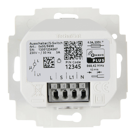
3 Illustrations Front (using Busch-Jaeger as an example) Status LED Upper push-button position (left) Lower push-button position (left) Upper push-button position (right) Lower push-button position (right) - Page 13 Rear Phase Switched output (to consumer 1) (T1 - T2) Switched output (to consumer 2) (T3 - T4) Neutral...
-
Page 14: Connection Diagram
4 Connection diagram Connection example:... -
Page 15: Installation
4.1 Installation Flush-mounted box (DIN 49073-1) Frame Rocker switch Balancing frame TechniSat Series switch... -
Page 16: Terminal Connection
4.2 Terminal connection The terminal on the series switch is designed for cables of 1.5 mm² (fixed) or 1 mm² (flexible with clamping sleeve). The conductor must be stripped by 10 mm. The conductor can be connected and disconnected again by pressing the push-button with a suitable tool, e.g. -
Page 17: Integration Into The Z-Wave Network (Adding/Inclusion)
10 minutes for your new device to be added to your Z-Wave network. The Z-Wave SmartStart QR code can be found on the back of the TechniSat series switch, on the front of this manual or on the device box. Activate the SmartStart function in your primary Z-Wave controller and follow the operating steps to add a device. -
Page 18: Manual Set-Up
After the wiring and power supply have been properly set up, switch the fuse back on. After restoring the power supply, it may take up to 10 minutes for the TechniSat series switch to be added to your Z-Wave network. 5.2 Manual set-up WARNING Only trained personnel (electricians) may connect devices without plugs. -
Page 19: Removing The Device From The Network
Press the upper push-button position (T1) 3 times within one second. The LED lights up red while the TechniSat series switch is being added to the Z-Wave network. If the set-up has been successful, the LED lights up green for 5 seconds. -
Page 20: Configuration
If the set-up has been successful, the LED lights up alternately red / green for about 5 seconds. 6 Configuration The following settings can be made. The configuration is carried out via the primary Z-Wave controller. Parameter Description Size Value Default (bytes) Activates / Deactivates:... -
Page 21: Supported Association Groups
Parameter Description Size Value Default (bytes) Switch operation 0 - T1 & T3 switch of push buttons output on, T1 - T4 T2 & T4 switch output off. 1 - T1 - T4 switch output on or off respectively 7 Supported association groups Main device: Name Maximum... - Page 22 Connection 1: Name Maximum CC commands group members Lifeline - Meter report - Switch binary report - Notification report Switch - Basic set State 1 Connection 2: Name Maximum CC commands group members Lifeline - Meter report - Switch binary report - Notification report Switch - Basic set...
-
Page 23: Basic Command Class
Members of association group 2 are controlled with Basic_Set commands of the basic command class. If the TechniSat series switch is switched on, a Basic_Set (0 x FF) command is sent to members of association group 2. If the TechniSat series switch is switched off, a Basic_Set (0 x 00) command is sent to members of association group 2. - Page 24 Command class Version Required Z-Wave safety levels Basic highest permitted Binary switch highest permitted Central scene highest permitted Configuration highest permitted Device reset locally highest permitted Firmware update meta data highest permitted Manufacturer specific highest permitted Meter highest permitted Multi-channel highest permitted Multi-channel association highest permitted...
- Page 25 Command class Version Required Z-Wave safety levels Version highest permitted Z-Wave Plus info none Connection 1 & 2: Association highest permitted Association group information highest permitted Basic highest permitted Binary switch highest permitted Meter highest permitted Multi-channel association highest permitted Notification highest permitted Security 0...
-
Page 26: Central Scene Command Class
11 Central scene command class The TechniSat series switch can also be used as a scene switch. In the default configuration (page 19, parameter 1), the series switch sends Z-Wave command class central scene trigger notifications to the primary Z-Wave controller when push-button positions T1, T2, T3 or T4 are pressed multiple times. -
Page 27: Firmware Update
12 Firmware update The firmware for the TechniSat series switch can be updated via the Z-Wave network. For safety reasons, an update must be confirmed manually on the TechniSat series switch. Proceed as follows to update the firmware: Observe all instructions and pop-ups on your primary Z-Wave controller. -
Page 28: Technical Data
13 Technical data Special features Flush-mounted series switch Z-Wave Plus Security S2 SmartStart Overload protection Compatible with multiple German switch system manufacturers*: Merten - M1 series, Busch-Jaeger - Duro 2000 series, Gira - System 55 series, power supply 230 V AC +/- 10 % Frequency 50 Hz +/- 10 % Nominal load current of outputs... - Page 29 Protection type (housing) IP20 Measurement accuracy (performance) ±0.3 W 1 W - 10 W ±0.4 W 10 W - 50 W ±3 % > 50 W Status LED Red = device is logged into the network. Flashing red = overload detected. Green (5 seconds) = device successfully logged in.
- Page 32 11032021ORV9 2238031871200...
Need help?
Do you have a question about the Switch Series and is the answer not in the manual?
Questions and answers