Table of Contents
Troubleshooting

Related Manuals for Cray CX1


Summary of Contents for Cray CX1
- Page 1 CRAY CX1 Personal Cluster User Manual CRAY CX1 High Performance Personal Cluster User Manual Revision 1.4 CRAY CX1 Personal Cluster Page 1 of 74 Copyright © 2008. All rights reserved. Proprietary Information.
- Page 2 User Manual CUSTOMER SERVICE CRAY Customer Service will respond efficiently to communicate your information and issues to the appropriate personnel. Be sure to mention the product serial # in order for the information to be directed to the right personnel.
- Page 3 In particular, CRAY shall not have liability for any hardware, software, or data stored or used with the product, including the costs of repairing, replacing, integrating, installing or recovering such hardware, software, or data.
- Page 4 CRAY CX1 Personal Cluster User Manual Conventions Used in this Manual Special attention should be given to the following symbols for proper installation and to prevent damage done to the components or to personal injury. It is extremely important to learn the correct and safe use of this product. Various kinds of cautionary labels with wording and symbols are used in this manual where necessary.
- Page 5 CRAY CX1 Personal Cluster User Manual REVISION RECORD TABLE Revision Changes Pages Initial Release System Installation FRU Lists Troubleshooting Certifications Logos added CN5400 blade removed CN4800 blade removed CN5500 blade added CRAY CX1 Personal Cluster Page 5 of 74 Copyright © 2008. All rights reserved. Proprietary Information.
-
Page 6: Table Of Contents
INSTALLING CPU AND HEAT SINKS ..............48 3.2.6 INSTALLING DIMMS ..................51 3.2.7 INSTALLING AND REMOVING A BLADE FROM THE CX1 CHASSIS ........53 CS5504 STORAGE BLADE ................... 54 3.3.1 CS5504H HOT-SWAP STORAGE BLADE..............54 ... - Page 7 MAIN SCREEN ....................59 ALARM ......................60 CONTROLLING THE SYSTEM POWER ..............61 CX1 SERVER MANAGER ..................61 USING THE CONFIGURATION MANAGER ..............63 COMPONENT STATUS ..................66 ...
- Page 8 Figure 3-8 LCD Touch Panel ..................34 Figure 3-9 Serial Port Setting ..................35 Figure 3-10 LCD Display for the CX1 ................35 Figure 3-11 Fan Cooling System ..................36 Figure 3-12 Power Supply ..................... 37 ...
- Page 9 CRAY CX1 Personal Cluster User Manual LIST OF TABLES Table 3-1 HCA Specifications ..................32 Table 3-2 CN5500 Specifications ..................43 Table 3-3 Jumper /LEDs ....................44 Table 3-4 CN5500 Connectors ..................45 Table 4-1 Troubleshooting .................... 57 ...
- Page 10 Details the initial setup of the CX1. Section 3.0 SYSTEM OVERVIEW: Details the various components comprising the CX1. Section 4.0 SOFTWARE: Details the installation of all supported operating systems of the CX1. Section 5.0 TROUBLESHOOTING: Details basic troubleshooting techniques for the CX1. Section 6.0 APPENDIX:...
- Page 11 Restriction of Hazardous Substances PECI Platform Environment Control Interface Serial Digital Interface Transmission Control Protocol Thermal Management 2 WEEE Waste Electrical and Electronic Equipment CRAY CX1 Personal Cluster Page 11 of 74 © Copyright 2008, Cray Inc. All rights reserved. Proprietary Information.
-
Page 12: Introduction
High Performance Computer (HPC) is a compact, self-contained server which provides power, cooling, management and networking functions. A single chassis can accommodate up to eight blade units in various configurations. The CX1 is a versatile cluster configurable with: Dual socket compute node ... -
Page 13: Quality Certifications And Safety
CRAY CX1 Personal Cluster User Manual 1.1 QUALITY CERTIFICATIONS AND SAFETY The CX1 meets the following certification requirements for the license duration: ISO 9001:2000 ISO 14001 RoHS5, RoHS6 FCC Regulation KCC Regulation CSA Regulation ... -
Page 14: Electrical Safety Precautions
Electrostatic-Discharge (ESD) can damage electronic components. To prevent damage to your system board, it is important to handle IC boards or modules very carefully. CRAY CX1 Personal Cluster Page 14 of 74 © Copyright 2008, Cray Inc. All rights reserved. Proprietary Information. -
Page 15: Electrical Discharge Precautions
Does not require a dedicated computer room, and is 92% power efficient. Uses regular office power outlets (20A – 110/240V). Note: A fully-populated CX1 system requires 2 dedicated 20A (110/240V) circuits. CRAY CX1 Personal Cluster Page 15 of 74 ©... -
Page 16: Product Checklist
External USB (M/M) cables 1 to 8 Gigabit cables 1 to 8 (Optional) Infiniband cables (Optional) Chassis cart (Optional) Rack mounting rail kit CRAY CX1 Personal Cluster Page 16 of 74 © Copyright 2008, Cray Inc. All rights reserved. Proprietary Information. -
Page 17: System Installation
Before unpacking, verify the status of the Tip and Tell sensors, present to indicate any excessive impact during shipment. If the indicators are BLUE indicating excessive shock, please contact CRAY immediately for instructions on how to proceed. CRAY CX1 Personal Cluster Page 17 of 74 ©... -
Page 18: Figure 2-1 Packaging
[2] Chassis Cart Box [3] Rail Box [4] Main Chassis Box [5] Power Supply Box [6] Blade Box [7] Cables [8] Accessories Figure 2-1 Packaging CRAY CX1 Personal Cluster Page 18 of 74 © Copyright 2008, Cray Inc. All rights reserved. Proprietary Information. -
Page 19: Assembly
Figure 2-2 Chassis Cart CRAY CX1 Personal Cluster Page 19 of 74 © Copyright 2008, Cray Inc. All rights reserved. Proprietary Information. -
Page 20: Figure 2-3 Chassis Assembly
To ensure that the blade has been properly installed, verify that the handle’s locking mechanism secured into the notch on the chassis, securing the blade in place. CRAY CX1 Personal Cluster Page 20 of 74 © Copyright 2008, Cray Inc. All rights reserved. Proprietary Information. -
Page 21: Cabling
InfiniBand switch, thus providing the CX1 with a high-bandwidth low-latency communication medium. Two types of InfiniBand cables are available for the CX1, and the correct type of cable must be selected, depending on which hardware is providing the connectivity to the InfiniBand switch. -
Page 22: System Startup
Description Power Switch (Zone A) Power Switch (Zone B) Figure 2-6 System Startup CRAY CX1 Personal Cluster Page 22 of 74 © Copyright 2008, Cray Inc. All rights reserved. Proprietary Information. -
Page 23: Zone Division
Power Switch (Zone B) Power Outlet (Zone A) 20 Amp 110/240 Volts Power Outlet (Zone B) 20 Amp 110/240 Volts Figure 2-7 CX1 Zones CRAY CX1 Personal Cluster Page 23 of 74 © Copyright 2008, Cray Inc. All rights reserved. Proprietary Information. -
Page 24: Rackmount Installation
Before unpacking, verify status of the Shock & Tilt sensors for excessive impact. If indicators are Blue indicating excessive shock, please contact CRAY for instructions. CRAY CX1 Personal Cluster Page 24 of 74 © Copyright 2008, Cray Inc. All rights reserved. Proprietary Information. -
Page 25: Figure 2-8 Rail Mounting Instructions
CRAY CX1 Personal Cluster User Manual Figure 2-8 Rail Mounting Instructions CRAY CX1 Personal Cluster Page 25 of 74 © Copyright 2008, Cray Inc. All rights reserved. Proprietary Information. -
Page 26: Figure 2-9 Rackmounted Cx1
Figure 2-9 Rackmounted CX1 Handle the chassis with extreme care making sure the rails slide smoothly. CRAY CX1 Personal Cluster Page 26 of 74 © Copyright 2008, Cray Inc. All rights reserved. Proprietary Information. -
Page 27: System Overview
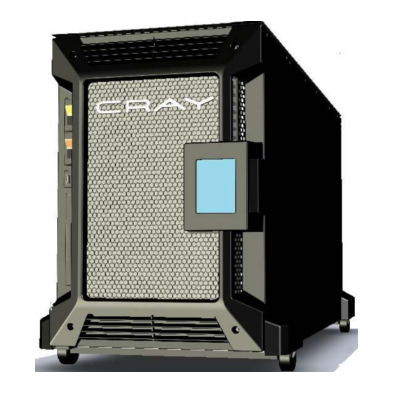
The following views display the CRAY CX1 system’s key components: Figure 3-1 CRAY CX1 System CRAY CX1 Personal Cluster Page 27 of 74 © Copyright 2008, Cray Inc. All rights reserved. Proprietary Information. -
Page 28: Cray Cx1 Chassis Overview
Blades Power Supplies Cable Connectors Chassisr Active Noise Control Module Front Panel Right Cover Wheel-mounted Chassis Cartl Figure 3-2 Front Exploded View CRAY CX1 Personal Cluster Page 28 of 74 © Copyright 2008, Cray Inc. All rights reserved. Proprietary Information. -
Page 29: Figure 3-3 Rear Chassis View
Switch 16-port Gigabit Switch 2- 120 VAC (20 A) Power Outlets 3 x USB External Passthrough Ports Figure 3-3 Rear Chassis View CRAY CX1 Personal Cluster Page 29 of 74 © Copyright 2008, Cray Inc. All rights reserved. Proprietary Information. -
Page 30: Figure 3-4 Front View
User Manual Description Zone A Power Switch Zone B Power Switch USB Connectors DVD-ROM drive LCD Touch Screen Panel Figure 3-4 Front View CRAY CX1 Personal Cluster Page 30 of 74 © Copyright 2008, Cray Inc. All rights reserved. Proprietary Information. -
Page 31: Infiniband
Power/Status LED External InfiniBand Port (24) Port Physical Link (Green) Port Status LED (Yellow) Port Activity LED (Green) Figure 3-5 InfiniBand CRAY CX1 Personal Cluster Page 31 of 74 © Copyright 2008, Cray Inc. All rights reserved. Proprietary Information. -
Page 32: Hca Card And Riser Card
Linux and Windows drivers InfiniBand Compatible Verbs API Linux management and applications package available Various upper layer protocols ROHS-R5 Compliant CRAY CX1 Personal Cluster Page 32 of 74 © Copyright 2008, Cray Inc. All rights reserved. Proprietary Information. -
Page 33: Gigabit Switch
Play, CE, FCC Class A certified, C-Tick, CISPR 22 Class A, cUL, UL 1950, VCCI Class A ITE, EN55022 Class A Figure 3-7 16-Port Gigabit Switch CRAY CX1 Personal Cluster Page 33 of 74 © Copyright 2008, Cray Inc. All rights reserved. Proprietary Information. -
Page 34: Lcd Touch Panel Computer
The LCD module runs on the Microsoft Windows CE OS. Description Ethernet LAN port RS232 port USB port Touch Panel Figure 3-8 LCD Touch Panel CRAY CX1 Personal Cluster Page 34 of 74 © Copyright 2008, Cray Inc. All rights reserved. Proprietary Information. -
Page 35: Figure 3-9 Serial Port Setting
CRAY CX1 Personal Cluster User Manual The LCD touch panel can control the CX1’s power on and off, fan speeds, activation of specific blades, all the while displaying critical system information such as fan speeds and temperatures. Communication from the LCD to the CX1 is managed through the RS-232 serial standard. -
Page 36: Cooling & Active Noise Control
Each fan produces 330 CFM airflow. The active noise control module is powered by the fan converter module, located inside the CX1, at 24V. The airflow of the fans may be adjusted on the front-panel LCD, while the two fans’ speed is monitored by the fan converter module, providing an alarm should a fan fail and need to be serviced. -
Page 37: Power Supply
CPU modules connected in Zone B cannot be powered-up until the Zone A Power breaker switch is ON. Description Power Supply Module Power Supply Module with Redundancy Figure 3-12 Power Supply CRAY CX1 Personal Cluster Page 37 of 74 © Copyright 2008, Cray Inc. All rights reserved. Proprietary Information. -
Page 38: Dvd / Usb Passthrough
DVD/USB pass-through to physically connect to any DVD or peripheral requiring a USB connection, from any blade of either Zone A or Zone B. Figure 3-13 USB Passthrough CRAY CX1 Personal Cluster Page 38 of 74 © Copyright 2008, Cray Inc. All rights reserved. Proprietary Information. -
Page 39: Cn5500 Compute Blade
Execution, Advanced Transfer Cache, Streaming SIMD Extensions 4 (SSE4), and Thermal Monitor 2 (TM2) Technology. These features allow the motherboard to operate at high speeds and optimal power management. There are two models available for the CX1 compute blade: 1. CN5500-XD This blade’s motherboard has onboard InfiniBand;... -
Page 40: Removing The Blade Cover
To re-insert the cover, align the cover with the casing and slide it into place. Step 5: The blade locking latches should snap and lock the cover in place. Figure 3-15 Sliding Blade Cover CRAY CX1 Personal Cluster Page 40 of 74 © Copyright 2008, Cray Inc. All rights reserved. Proprietary Information. -
Page 41: Figure 3-16 Inside View Of A Cn550 Blade
96 GB maximum) PCI Express x16 expansion slot InfiniBand controller (available on the CN5500-XD blade only) Figure 3-16 Inside View of a CN550 Blade CRAY CX1 Personal Cluster Page 41 of 74 © Copyright 2008, Cray Inc. All rights reserved. Proprietary Information. -
Page 42: Cn5500 Motherboard
ESB2. In addition, the 5500 chipset offers a wide range of RAS features, including memory interface ECC, x4/x8 Single Device Data Correction, CRC, parity protection, memory mirroring and memory sparing. CRAY CX1 Personal Cluster Page 42 of 74 © Copyright 2008, Cray Inc. All rights reserved. Proprietary Information. -
Page 43: Cn5500 Motherboard Specifications
• One external QSFP InfiniBand connector (available on the CN5500-XD blade only) Dimensions 16.0" x 6.5" (406.4 mm x 165.1 mm) Table 3-2 CN5500 Specifications CRAY CX1 Personal Cluster Page 43 of 74 © Copyright 2008, Cray Inc. All rights reserved. Proprietary Information. -
Page 44: Figure 3-18 Motherboard Layout
(Rear) Unit Identifier (UID) LED Indicator LEB1 Infi niBand Link LED LEB2 BMC Activity LED Table 3-3 Jumper /LEDs Figure 3-18 Motherboard Layout CRAY CX1 Personal Cluster Page 44 of 74 © Copyright 2008, Cray Inc. All rights reserved. Proprietary Information. -
Page 45: Table 3-4 Cn5500 Connectors
Note 2: The 4-pin Auxiliary PWR Connector is used as a power output to the HDDs only. CRAY CX1 Personal Cluster Page 45 of 74 © Copyright 2008, Cray Inc. All rights reserved. Proprietary Information. -
Page 46: Acpi Features
3.2.4 ACPI FEATURES The CX1’s motherboards have built-in Advanced Configuration and Power Interface (ACPI) specifications which defines a flexible and abstract hardware interface that provides a standard way to integrate power management features throughout a PC system, including its hardware, operating system and application software. -
Page 47: Figure 3-19 Block Diagram Of The 5500 Series Processor Platform
CRAY CX1 Personal Cluster User Manual Figure 3-19 Block Diagram of the 5500 Series Processor Platform CRAY CX1 Personal Cluster Page 47 of 74 © Copyright 2008, Cray Inc. All rights reserved. Proprietary Information. -
Page 48: Installing Cpu And Heat Sinks
Electrostatic-Discharge (ESD) can damage electronic components. To prevent damage to your system board, it is important to handle IC boards or modules very carefully. CRAY CX1 Personal Cluster Page 48 of 74 © Copyright 2008, Cray Inc. All rights reserved. Proprietary Information. -
Page 49: Figure 3-21 Cpu Install
CRAY CX1 Personal Cluster User Manual Figure 3-21 CPU Install CRAY CX1 Personal Cluster Page 49 of 74 © Copyright 2008, Cray Inc. All rights reserved. Proprietary Information. - Page 50 8. Finish the installation by fully tightening all four screws. Once installed, it is not recommended to remove either the heatsink or CPU. CRAY CX1 Personal Cluster Page 50 of 74 © Copyright 2008, Cray Inc. All rights reserved. Proprietary Information.
-
Page 51: Installing Dimms
4 GB of memory. different speeds, voltages, sizes or types on the same motherboard. CRAY CX1 Personal Cluster Page 51 of 74 © Copyright 2008, Cray Inc. All rights reserved. Proprietary Information. -
Page 52: Figure 3-22 Dimm Install
CRAY CX1 Personal Cluster User Manual Figure 3-22 DIMM Install CRAY CX1 Personal Cluster Page 52 of 74 © Copyright 2008, Cray Inc. All rights reserved. Proprietary Information. -
Page 53: Installing And Removing A Blade From The Cx1 Chassis
CRAY CX1 Personal Cluster User Manual 3.2.7 INSTALLING AND REMOVING A BLADE FROM THE CX1 CHASSIS The blade module is installed or removed using a release latch located at the left bottom of the blade. Figure 3-23 Blade Release Latch Assembly When mounting the Server Blade, care must be taken to align the Blade with slots and slide carefully. -
Page 54: Cs5504 Storage Blade
Figure 3-25 Angle View of the Fixed Storage Blade Description CN5500 Compute Blade Fixed Storage Node Four SATA 3.5” Hard Disk Drives CRAY CX1 Personal Cluster Page 54 of 74 © Copyright 2008, Cray Inc. All rights reserved. Proprietary Information. -
Page 55: Cv5501 Visualization Blade
NVIDIA Quadro FX 4600 Graphics Card Description CN5500 Compute Blade Visualization Node (containing either a graphics or GPU card) Figure 3-29 Front View of CV5501 Blade CRAY CX1 Personal Cluster Page 55 of 74 © Copyright 2008, Cray Inc. All rights reserved. Proprietary Information. -
Page 56: Troubleshooting
Most likely an OS setup or try to boot from FC4 rescue initialized an error message appears configuration issue. Consult Operating System documentation. CRAY CX1 Personal Cluster Page 56 of 74 © Copyright 2008, Cray Inc. All rights reserved. Proprietary Information. -
Page 57: Table 4-1 Troubleshooting
Are there any errors mentioning bugs in loaded module? Hardware needs to be examined for possible mal-function. Table 4-1 Troubleshooting CRAY CX1 Personal Cluster Page 57 of 74 © Copyright 2008, Cray Inc. All rights reserved. Proprietary Information. -
Page 58: Appendix 1: Lcd Display Installation And Operating Guide
Before using the system, you must manually declare each module that is installed in the CX1 server. This will allow the correct display of the alarms and the status of each component. The CX1 server can accommodate up to eight (8) blades (computing node, graphic node, GPU node or storage node). It is powered from two (2) independent power sources, each one feeding half of the machine (Zone A and Zone B). -
Page 59: Using The Lcd Display
This button will flash if there is an alarm in the system. To view the alarm, push the button. This button is used to control the power of every blade of the system at once. The CX1 button allows configuring the server and having access to a detailed view of each component. -
Page 60: Alarm
When this occurs, it is important for the user to acknowledge the indicated alarms and possible faults on the CX1 server before resuming operations. To do so, the user must press the alarm button the main screen and acknowledge the faults that appear on the alarm screen:... -
Page 61: Controlling The System Power
Perform a hard power off on all blades. Go back to the Main Screen. 5.6 CX1 SERVER MANAGER From the main screen, hit the CX1 server icon (bottom center) . The following screen will be displayed. CRAY CX1 Personal Cluster Page 61 of 74 ©... - Page 62 This button allows you to start/stop/reset the selected blade. This button will flash if there is an alarm in the selected component. To view the alarm detail, push the button. CRAY CX1 Personal Cluster Page 62 of 74 © Copyright 2008, Cray Inc. All rights reserved. Proprietary Information.
-
Page 63: Using The Configuration Manager
The following screen will be displayed. Select the name of the server and the temperature display setting (°C or °F) and hit the apply button. Hit the escape button and use the up/down arrow to select another CX1 server component. Using the configuration manager, accessed again with the use of the button , the user can define: ... - Page 64 Furthermore, it allows the user to define whether or not if the power supply module is populated by checking next to “Installed module type”: CRAY CX1 Personal Cluster Page 64 of 74 © Copyright 2008, Cray Inc. All rights reserved. Proprietary Information.
- Page 65 Automatic, by checking the “Auto Fan Control” checkbox, as shown in the following screen. Note that if this option is checked, the user cannot manually change the fan speed. CRAY CX1 Personal Cluster Page 65 of 74 © Copyright 2008, Cray Inc. All rights reserved. Proprietary Information.
-
Page 66: Component Status
When done, hit the Escape (Esc) button to go back to the previous menu. 5.8 COMPONENT STATUS To display the status of a component on the CX1 server, select the desired component and hit the status button If a blade is selected, the following screen will appear, showing the firmware version of the blade’s bus... - Page 67 If the fan module is selected, the following screen will appear, showing the firmware version of the fan controller module, its state, temperature, power consumption, top and bottom fans’ speed, input status and failure status: CRAY CX1 Personal Cluster Page 67 of 74 © Copyright 2008, Cray Inc. All rights reserved. Proprietary Information.
-
Page 68: Screensaver
To turn the LCD display program off and access the start menu, hit the power button on the lower right of the main screen. CRAY CX1 Personal Cluster Page 68 of 74 © Copyright 2008, Cray Inc. All rights reserved. Proprietary Information. - Page 69 To restart the system, use the reboot logo on the hidden WinCE Start status bar. NOTE: To unhide the status bar, touch the grey bar at the bottom of the screen shown above. CRAY CX1 Personal Cluster Page 69 of 74 © Copyright 2008, Cray Inc. All rights reserved. Proprietary Information.
-
Page 70: Updating The Lcd Application
Plug the USB key into the mini-USB dongle provided with the CX1 system. With the USB key connected to the dongle, plug the mini-USB dongle into the small opening on the CX1's front bezel. Once the USB dongle is connected, and the CX1 LCD is powered on, the following should be displayed: Click the power button (circled in the preceding picture above), at which point the System commands screen (below) will be seen. - Page 71 With the desktop now showing (shown below, left), click the grey bar at the bottom of the screen, in order to make the hidden taskbar show up (shown below, right). Next, click the “Start” button (shown below). CRAY CX1 Personal Cluster Page 71 of 74 © Copyright 2008, Cray Inc. All rights reserved. Proprietary Information.
- Page 72 Double-click on “USB Hard Disk” (shown below, left). The contents of the USB Hard Disk will then be displayed (shown below, right). CRAY CX1 Personal Cluster Page 72 of 74 © Copyright 2008, Cray Inc. All rights reserved. Proprietary Information.
- Page 73 Double-click on the “UPDATE.BAT” file, at which point the update script will be executed. The next screens shown will be a “Pocket CMD” screen (shown below, left), followed by a “CRAY” screen showing the LCD application starting up (shown below, right).
-
Page 74: Cray Cx1 Personal Cluster
Therefore, if your system is not fully-populated, the missing blades will be flashing after the update and those not present will need to be un-selected. Unplug the USB dongle from the LCD screen. This completes the update of the Cray CX1 LCD application. CRAY CX1 Personal Cluster Page 74 of 74 ©...
Need help?
Do you have a question about the CX1 and is the answer not in the manual?
Questions and answers