Table of Contents
Advertisement
Quick Links
Advertisement
Table of Contents

Subscribe to Our Youtube Channel
Related Manuals for DELTA DORE DELTA 8000 BT


Summary of Contents for DELTA DORE DELTA 8000 BT
- Page 1 DELTA 8000 BT Technical unit for Delta 8000 system Installation instructions...
-
Page 2: Table Of Contents
CONTENTS 1/ Overview of the technical unit 2/ Mounting and connecting the technical unit 3/ Connecting the technical unit's inputs/outputs 4/ Application examples 4.1 Hard-wired 4.2 Wireless (option) 4.3 Hybrid hard-wired and wireless 4.4 Extension (option) 5/ Switch configuration 6/ Associating a room thermostat with a technical unit 6.1 With a Room Thermostat (RT) 6.2 With a Programmable Room Thermostat (PRT) -
Page 3: 1/ Overview Of The Technical Unit
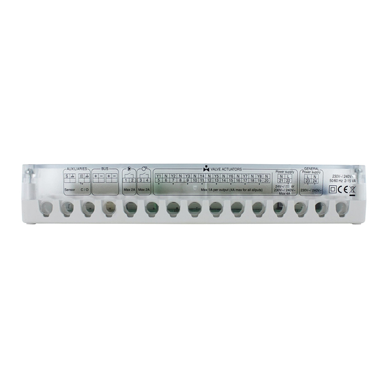
2/ MOUNTING AND CONNECTING THE 1/ OVERVIEW OF THE TECHNICAL UNIT TECHNICAL UNIT Circulator LED Status LED Burner LED Confi guration Valve output LEDs Ê switches ❶ Remove the cover Ë ❷ Mount the unit with a set of screws/sprigs compatible with the substrate (not included). -
Page 4: 3/ Connecting The Technical Unit'sinputs/Outputs
3/ CONNECTING THE TECHNICAL UNIT'S INPUTS/OUTPUTS Switch off the mains power before handling the device. ❶ Water monitoring input (option) by CTN sensor or dew point sensor (according to SW8 configuration) ❷ Change-over input or output (according to SW6 configuration). If change-over output: voltage off load <... -
Page 5: 4/ Application Examples
4/ APPLICATION EXAMPLES BUS 1 BUS 2 1-> 8 sorties max. 4.1 HARD-WIRED 30m max. Example 3: Regulation with room by room programming Example 1: Room by room regulation without programming PRT: Programmable Room Thermostat RT: Room thermostat PRT zone N PRT zone 2 zone 2 RT zone N... -
Page 6: Wireless (Option)
30m max. 4/ APPLICATION EXAMPLES BUS 1 BUS 2 4.2 WIRELESS (OPTION) 4.3 HYBRID HARD-WIRED AND WIRELESS Associating the radio/Bus gateway with the technical unit will enable access to the range's Wireless and hard-wired solutions can be used concomitantly on the same installation : 1->... -
Page 7: 5/ Switch Configuration
Contact open = Heat mode Transmitter type Heater Absence of dew point measurement or sensor with a Delta Dore condensation sensor (For cooling only, Ceiling or ductable Type of 'water shuts the system down if condensation is detected). Zone thermostat... -
Page 8: With A Programmable Room Thermostat (Prt)
6/ ASSOCIATING A ROOM THERMOSTAT WITH 7/ CONFIGURING THE TECHNICAL UNIT A TECHNICAL UNIT 6.2 WITH A PROGRAMMABLE ROOM 7.1 WITH A ROOM THERMOSTAT (RT) THERMOSTAT (PRT) ❶ From the OFF mode, press and hold the 2nd button from the left for 5 seconds. ❶... -
Page 9: With A Programmable Room Thermostat (Prt) Or Programmer (Prog)
8/ RESTORING THE TECHNICAL UNIT TO 7/ CONFIGURING THE TECHNICAL UNIT FACTORY SETTINGS 7.2 WITH A PROGRAMMABLE ROOM THERMOSTAT (PRT) 8.1 WITH A ROOM THERMOSTAT (RT) OR PROGRAMMER (PROG) ❶ From the OFF mode, Simultaneously press and hold the 1st and 3rd buttons from the left ( ) for 20 seconds. -
Page 10: With A Programmable Room Thermostat (Prt) Or Programmer (Prog)
8/ RESTORING THE TECHNICAL UNIT TO 9/ WATER TEMPERATURE MONITORING FACTORY SETTINGS The multizone kit offers an optional water network temperature monitoring function 8.2 WITH A PROGRAMMABLE ROOM THERMOSTAT (PRT) (hot and cold). This function protects the system from overheating in the water network (protection of OR PROGRAMMER (PROG) the slab and pipes) or from abnormally low temperature, which will generally lead to the formation of condensation on the flooring. -
Page 11: 10/ Troubleshooting
10/ TROUBLESHOOTING 11/ TECHNICAL CHARACTERISTICS When a defect is detected on the system, the symbol flashes on the room unit display. Press 'i' to display the type of defect. • Main power supply 230V~/240V~, +/-10%, 50/60 Hz, Check connection between the Green LED Bus defect •... - Page 12 www.deltadore.com...
Need help?
Do you have a question about the DELTA 8000 BT and is the answer not in the manual?
Questions and answers