
Related Manuals for tams elektronik ARTEMIS

Summary of Contents for tams elektronik ARTEMIS
- Page 1 Manual ARTEMIS Item no. 46-00117 for a sublevel with 32 nodes tams elektronik n n n...
-
Page 2: Table Of Contents
10. EU declaration of conformity............21 11. Declarations conforming to the WEEE directive......21 © 09/2020 Tams Elektronik GmbH All rights reserved. No part of this publication may be reproduced or transmitted in any form or by any means, electronic or mechanical, including photocopying, without prior permission in writing from Tams Elektronik GmbH. -
Page 3: Getting Started
Intended use The hub ARTEMIS is designed to be operated according to the instructions in this manual in model building, especially in digital model railroad layouts. Any other use is inappropriate and invalidates any guarantees. - Page 4 English ARTEMIS Package contents hub ARTEMIS one pluggable screw terminal for connection to the power supply 4 short-circuit jumpers a CD (containing the manual and further information) Required materials You will need a switching or plug-in power supply. Technical data: ...
-
Page 5: Safety Instructions
ARTEMIS English 2. Safety instructions Mechanical hazards Cut wires can have sharp ends and can cause serious injuries. Watch out for sharp edges when you pick up the PCB. Visibly damaged parts can cause unpredictable danger. Do not use damaged parts: recycle and replace them with new ones. - Page 6 English ARTEMIS Other dangers Children can cause any of the accidents mentioned above because they are inattentive and not responsible enough. Children under the age of 14 should not be allowed to work with this module. In schools, training centres, clubs and workshops, assembly must be supervised by qualified personnel.
-
Page 7: Operation Overview
ARTEMIS English 3. Operation overview 3.1. Background In the BiDi-Bus the maximum number of participants in one level or sublevel is limited to 32 nodes (e.g. interface, booster, accessory decoder, feedback modules) for technical reasons. In total up to 4 levels are permitted. With special nodes (the bus bridges or so-called "hubs") further sublevels can be added in the top 3... - Page 8 English ARTEMIS Note on the numbering of the nodes in the example: According to the BiDiB specification the user does not have to deal with numbers or addresses of the components. The numbers in the figure were dialled in analogy to the addresses that the components receive according to the BiDiB protocol.
-
Page 9: Artemis
According to the BiDiB specification, components that do not require additional power for their basic functions (e.g. feedback devices) obtain their power via the bus cable. ARTEMIS can provide up to 0.5 A for the supply of components in the sublevel. -
Page 10: Technical Specifications
English ARTEMIS 4. Technical specifications Features according to the BiDiB- Node, class "Interface" specification Optional Features: Firmware update Status of the BiDiB specification V0.7 Voltage supply 12 – 18 V d.c. voltage Current consumption max. 25 mA (without connected devices) -
Page 11: Connecting Artemis
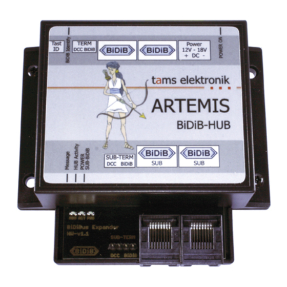
ARTEMIS English 5. Connecting ARTEMIS 5.1. Pin assignment Power Voltage supply (12 – 18 V direct voltage) BiDi-Bus Main level TERM Final jumper DCC BiDiB DCC/BiDiB termination SUB-TERM Final jumper DCC BiDiB DCC/BiDiB termination Sub-level BiDi-Bus Page 11... -
Page 12: Connection Of The Power Supply
English ARTEMIS 5.2. Connection of the power supply Use a separate plug-in or switching power supply for ARTEMIS. Technical data: Output voltage: 12 - 18 V direct voltage (DC) Output current: at least 1 A Please note : Do not use an AC transformer or AC power supply unit as the power supply. -
Page 13: Connection To The Bidi-Bus
English 5.3. Connection to the BiDi-Bus In terms of the BiDiB specification, ARTEMIS is a node that is operated together with up to 31 other nodes on one level. At the same time ARTEMIS is the interface for a subordinate level with up to 31 further nodes. - Page 14 ARTEMIS Setting the termination jumpers If the ARTEMIS hub is installed at one end of a BiDiB line (i.e. only one of the two BiDiB ports of the main or sub level has an RJ-45 cable), you must plug in the two jumpers for the DCC and BiDiB termination of the level concerned.
-
Page 15: Settings
6.1. Identify button To identify an ARTEMIS bus bridge in the screen display of the control software, press the Identify button on the board. The associated BiDiB node is then highlighted on the screen and the LED on the hub flashes. -
Page 16: Operation
English ARTEMIS 7. Operation The LEDs indicate the operating states and error messages. Display of the operating states Power on fast flickering Device in operation double flashing Registration on the bus was refused → Section 8 Identify no connection to the BiDi bus... - Page 17 → Section 8 Error messages Power on 10 x fast flashing No bootloader found / no Identify firmware update possible. Message → Contact the Tams Elektronik Hotline. Power on continuous flashing EEPROM faulty. Identify → Perform a firmware update Message →...
-
Page 18: Check List For Troubleshooting
BiDiB nodes are interrupted. Check the connection(s). Possible cause: The terminating jumpers are not plugged in although ARTEMIS is installed at the end of one or both BiDiB lines or The termination jumpers are plugged in, although ARTEMIS is not installed at one end of one or both BiDiB lines. - Page 19 ARTEMIS English Hotline If problems with your module occur, our hotline is pleased to help you (mail address on the last page). Repairs You can send in a defective module for repair (address on the last page). In case of guarantee the repair is free of charge for you. With damages not covered by guarantee, the maximum fee for the repair is 50 % of the current sales price according to our valid price list.
-
Page 20: Guarantee Bond
English ARTEMIS 9. Guarantee bond For this product we issue voluntarily a guarantee of 2 years from the date of purchase by the first customer, but in maximum 3 years after the end of series production. The first customer is the consumer first... -
Page 21: Eu Declaration Of Conformity
ARTEMIS English 10. EU declaration of conformity This product conforms with the EC-directives mentioned below and is therefore CE certified. 2004/108/EG on electromagnetic. Underlying standards: EN 55014-1 and EN 61000-6-3. To guarantee the electromagnetic tolerance in operation you must take the following precautions: ... - Page 22 English ARTEMIS Page 22...
- Page 23 ARTEMIS English Page 23...
- Page 24 Information and tips: http://www.tams-online.de Warranty and service: Tams Elektronik GmbH Fuhrberger Straße 4 DE-30625 Hannover fon: +49 (0)511 / 55 60 60 fax: +49 (0)511 / 55 61 61 e-mail: modellbahn@tams-online.de...
Need help?
Do you have a question about the ARTEMIS and is the answer not in the manual?
Questions and answers