
Subscribe to Our Youtube Channel
Related Manuals for JETI model duplex


Summary of Contents for JETI model duplex
- Page 1 COMPLEX RADIO CONTROL SYSTEM COMPLEX RADIO CONTROL SYSTEM ® User Manual User Manual Receivers Rx Receivers Rx...
-
Page 2: Table Of Contents
COMPLEX RADIO CONTROL SYSTEM ENGLISH 1. Introduction ..................03 2. Technical data ..................05 2.1 Technical data of receivers outside the US ......05 2.2 Technical data of receivers for the US ........07 3. Installation ................... 09 3.1 Voltage Supply ................09 3.2 Operation .................. - Page 3 COMPLEX RADIO CONTROL SYSTEM 5. Receiver setup ..................14 5.1 Receiver Setup via the JETIBOX ..........14 5.1.1 Direct connection between a JETIBOX and the receiver ................. 14 5.1.2 Wireless connection between a JETIBOX with transmitter or DC/DS transmitter and the receiver ..14 5.2 Receiver set-up via the DC/DS transmitter ......
-
Page 4: Introduction
JETI Duplex receivers are designated for use with the DC/DS transmitters or the JETI transmitter modules in the 2.4 GHz frequency band. Duplex receivers are offered in a wide range of size and features to suit the numerous demands of our customers. - Page 5 From the very beginning bidirectional transmission has been a distinctive feature of the Duplex system, this not only handles telemetry data, but it also helps to ensure secure primarily transmission safety between the transmitter and receiver.
-
Page 6: Technical Data
COMPLEX RADIO CONTROL SYSTEM 2 Technical data 2.1 Technical data of receivers outside the US part 1 Basic Data R4 RES R7 nano Dimension [mm] 40x22x7 47x20x7 30x18x5 51x24x11 Weight [g] 2x100 2x100 1x30 2x200 Antenna length [mm] No. of channel outputs -10 up to -10 up to -10 up to... - Page 7 COMPLEX RADIO CONTROL SYSTEM 2.1 Technical data of receivers outside the US part 2 R14* R18* Rsat2 Basic Data Dimension [mm] 62x38x16 62x38x16 35x23x6 Weight [g] Antenna length [mm] 2x400 2x400 2x200 Serial No. of channel outputs communication -10 up to -10 up to -10 up to Temperature range [°C]...
-
Page 8: Technical Data Of Receivers For The Us
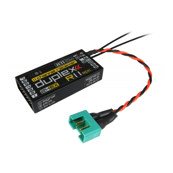
COMPLEX RADIO CONTROL SYSTEM 2.2 Technical data of receivers for the US part 1 (R4L (R5L (R6L R7plus Basic Data indoor) indoor) indoor) 10x22x7 38x20x7 47x20x7 43x24x11 51x24x11 Dimensions [mm] 4,8 (4,5) 5,4 (5) Weight [g] 2x100 2x100 2x200 2x200 2x200 Antenna length [mm] (2x45) - Page 9 COMPLEX RADIO CONTROL SYSTEM 2.2 Technical data of receivers for the US part 2 R11 EPC* R14* R18* Basic Data 51x24x11 51x24x11 62x38x16 62x38x16 Dimensions [mm] Weight [g] 2x200 2x200 2x400 2x400 Antenna length [mm] No. of channel outputs -10 up to -10 up to -10 up to -10 up to...
-
Page 10: Installation
3.1 Voltage supply When designing the on-board wiring for your project, always pay attention to the voltage input range of your receivers and servos. You can connect supply voltage to the Duplex receivers as follows: - directly from the batteries... -
Page 11: Binding
COMPLEX RADIO CONTROL SYSTEM 3.3 Binding When using a new receiver or transmitter it is necessary to carry out the binding process between them. Transmission between the receiver and transmitter occurs in fully digital manner, therefore it is necessary to identify and share the addresses of each device communicating on the mutual 2.4GHz frequency band. -
Page 12: Receiver R7Nano
COMPLEX RADIO CONTROL SYSTEM seconds elapse the receiver returns to setup mode and the binding process must be repeated by starting again from step 3. If the binding process between receiver and transmitter was unsuccessful, try again. You may bind an arbitrary number of receivers to one transmitter. The receiver, however, can only be bound to one transmitter, i. - Page 13 COMPLEX RADIO CONTROL SYSTEM the red wire to the plus (+). Solder the yellow, white or orange wire to the signal (Π). SERVO SERVO - impuls JETIBOX - plus Sensor - minus Expander ELECTROSTATIC SENSITIVE DEVICE OBSERVE HANDLING PRECAUTIONS...
-
Page 14: Real Time Telemetry
This telemetry data is displayed according to user selections in the DC/DS transmitters and the JETIBOX profi. You will find more details in actual instruction manuals of the given Duplex EX equipment. 4.2 - 1st Generation Connect the JETIBOX to the transmitter module. Switch on the transmitter and connect the receiver voltage supply (see chapter „Voltage supply“). -
Page 15: Receiver Setup
COMPLEX RADIO CONTROL SYSTEM 5 Receiver setup 5.1 Receiver setup via the JETIBOX There are two receiver setup modes. The first is receiver setup via the JETIBOX, JETIBOX profi or JETIBOX emulation in the DC/DS transmitters, the second one is direct setup of the receiver with a DC/DS transmitter. -
Page 16: Receiver Set-Up Via The Dc/Ds Transmitter
COMPLEX RADIO CONTROL SYSTEM Wireless connection is only possible when a receiver is in“Normal“ mode (MeasureOrSetting->Main Setting ->Rx mode: Normal). The JETIBOX can be disconnected only after you disconnect the receiver voltage supply. You may monitor the on-board state of your receiver during your model‘s operation. -
Page 17: Receiver Menu
COMPLEX RADIO CONTROL SYSTEM Receiver menu 6.1 Overview of receiver data items The introductory display shows the receiver type. By pushing the R key (arrow down) more detailed data of receiver and transmitter can be displayed. Pairing - by pushing the U key (arrow up) pairing of the receiver with the transmitter will be executed. -
Page 18: Main Setting
COMPLEX RADIO CONTROL SYSTEM Volt Min / Act / Max - the receiver is checking the supply voltage and indicates the limit values and extremes which occurred during operation; at the same time it also shows the actual receiver voltage. Without switching on the paired transmitter the values MAX and MIN will not change, only the value of the actual voltage ACT will be updated. - Page 19 COMPLEX RADIO CONTROL SYSTEM This setup is for transmitter modules only. For the DC/DS transmitters, this alarm is set in the transmitter. Output Period - output signal period setup (initial setup for the Autosynchronizing mode with the transmitter). This parameter is fundamentally influencing servo behaviour.
- Page 20 COMPLEX RADIO CONTROL SYSTEM telemetry information with configuration possibilities of equipment connected to this bus, for instance by a DC/DS transmitter. This interface is physically accessible at the receiver output labeled „Ext.“. This configuration type is used, for instance, when receivers are connected for example to Central Box. JETIBOX, UDI - serial data output suitable for connection of devices with unidirectional UDI interface (e.g.
- Page 21 Duplex receiver for remote control) Clone unidirectional communication ź if you use several Duplex receivers in the model, for instance in ź connection with one transmitter module, then you should operate one of the receivers in „Normal“ mode and the others in „clone“...
-
Page 22: Out Pin Set
COMPLEX RADIO CONTROL SYSTEM Telemetry* -unidirectional communication is usable exclusively for telemetry transmission, for instance with the US version of the JETIBOX profi. This setup change requires longer pressing (press and hold) of the left or right push button. The receiver mode change is only accessible via the JETIBOX, see the „Receiver setup“... - Page 23 COMPLEX RADIO CONTROL SYSTEM Some of the receivers outputs may be assigned (see the table of receiver output assignments) to alternative functions. Description of alternative functions: - standard servo output - the throw of an actual channel is assigned to the output that uses the standard servo output form and is labelled CH xx.
- Page 24 COMPLEX RADIO CONTROL SYSTEM FS position - throw setup of selected FailSafe output position in case of signal loss FS speed - sets how quickly the throws move to the FailSafe positions in case of signal loss Pin Config - receiver pin config can be: Pin Config - servo standard impulse output for servos (-100% = 1ms, 0%= 1,5ms / ź...
- Page 25 COMPLEX RADIO CONTROL SYSTEM Assignment table of receiver outputs: R4 RES R sat2 • • • • • • • • • • • • • • • • • • • • •/° • • • • • • •...
- Page 26 COMPLEX RADIO CONTROL SYSTEM Assignment table of US version receiver outputs R4L, R5L, R6L, R7 plus R9 R4Li R5Li R6Li • • • • • • • • • • • • • • • • • • •/° • •...
-
Page 27: R4 Res
COMPLEX RADIO CONTROL SYSTEM 6.5 Receiver R4 RES R4 RES receiver has a special type of firmware designed for the competition category of electrically powered gliders (ERES). Measurements and height calculations are the same as the specifications of F5J category. Settings and telemetry are strictly limited according to the needs of the ERES competition. - Page 28 COMPLEX RADIO CONTROL SYSTEM The receiver can only be configured if the "motor shutdown pulse" is not exceeded after connecting the power supply (default setting 1,100 ms). Once a throttle pulse is exceeded, then the receiver can no longer be set until its power supply is reset. Settings can be made only by the DC/DS transmitter (in the "device explorer"...
- Page 29 COMPLEX RADIO CONTROL SYSTEM The motor is shutdown if: Set height is reached ● Set time is reached ● The throttle lever has been pulled below the set level ● The motor will be stopped, whichever occurs first (terms above). After stopping the motor, the motor cannot be restarted until the receiver power is disconnected and connected again and the receiver returns to the Ready status.
-
Page 30: Reset To Factory Defaults
7 Receiver update Duplex Rx receivers can be upgraded by a PC and a JETI USB adapter. You can find a detailed description of the update procedure on our website in the "technical support" section, or on our YouTube channel. - Page 31 Warranty and post warranty service is provided by the manufacturer. We wish you sucessful flying with the products of: JETI model s.r.o. Příbor, www.jetimodel.com...
- Page 32 COMPLEX RADIO CONTROL SYSTEM...
- Page 33 COMPLEX RADIO CONTROL SYSTEM Duplex-System EX: • Transmitter modules • Receivers • Telemetric sensors • Compatible accessories • Display units Main Advantages of the DUPLEX-System: • digital data transfer • system without crystals • safe operation • real time telemetric data transfer •...
Need help?
Do you have a question about the duplex and is the answer not in the manual?
Questions and answers