Advertisement
Quick Links
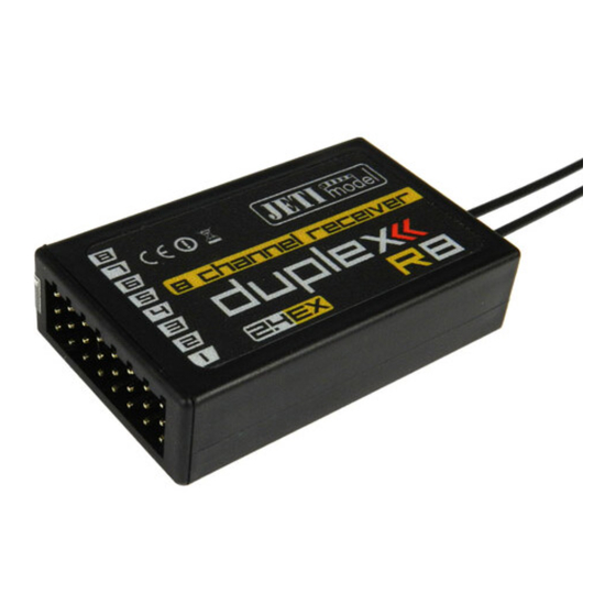
DUPLEX Rx
The DUPLEX Rx receiver line is assigned to operate with the transmitter modules DUPLEX Tx in the
2.4GHz band. The fully digital bidirectional communication between transmitter and receiver contributes to
the development of new chances in the model remote control branche.
DUPLEX receivers are not only following up with the JBC receiver line by keeping up their univerzality
and broad functional extent, but they additionally extend these functions due to the feasibility of the new
DUPLEX system. One of the most important advantages is the operation without crystals – watching
frequencies is a thing of the past, high interference resistance, far out of visibility range and continual
control of model conditions in the air as well as many other functions are new and formerly unknown
features.
DUPLEX Rx Receivers:
Basic Data
Dimensions
Weight
Antenna Length
Active Part of Antenna
# of Channel Outputs
Temperature Range
Supply Voltage
Average Current
Real Time Transmission
of Telemetric Data
Programming
Power Output
Receiver Sensitivity
Supply:
The receiver power supply may be carried out by NiCd cells, by a stabilized voltage from the controller
(in electric models) or by Li-xx cells combined with a voltage stabilizer like the MAX BEC. Always keep in
mind the recommended voltage range of the receiver and the used servos. If all receiver outputs are
engaged you may use an Y-cable for power supply. Supply batteries, BEC or Y-cables may be plugged
into any channel output. Do not use the output marked Ext. for RX-power supply.
Operation:
The DUPLEX system may be operated in the same way as any FM system. We recommend to switch
on the transmitter first and then the receiever. The transmitter confirms switching on of the receiver by a
short beep.
Installation:
Wrap the receiver in soft foam and place it as far as possible away from sources of interference
(servos, power electric motors). The antennas should be routed in such a manner that their active ends
make up an angle of 90° and are as far away as poss ible from each other. See to it that minimum bending
radii of the antenna cables are at least 1cm. The active part of the transmitting antenna should be straight
and far away from metal parts. If the model comprises a carbon fuselage it is advisable to place the active
parts of the antennas outside of the fuselage.
DUPLEX R4
38 x 20 x 8 mm
44 x 20 x 5 mm
5 g
2x 100 mm
30 mm
4
- 10 to + 85° C
- 10 to + 85° C
3,2 – 8,4V
39 mA
•
JETI BOX
6 dBm
-98 dBm
DUPLEX R5
DUPLEX R6
(R5 indoor)
45 x 24 x 12,5mm
5 g
(4 g)
2x 100 mm
(2x 45 mm)
30 mm
5
- 10 to + 85° C
3,2 – 8,4V
39 mA
•
JETI BOX
6 dBm
-98 dBm
DUPLEX R8
50 x 30 x 12,5 mm
11 g
2x 100 mm
2x 200 mm
30 mm
6
- 10 to + 85° C
3,2 – 8,4V
3,2 – 8,4V
40 mA
•
JETI BOX
JETI BOX
20 dBm
-100 dBm
-106 dBm
15 g
30 mm
8
48 mA
•
20 dBm
1
Advertisement

Subscribe to Our Youtube Channel
Related Manuals for JETI model DUPLEX R Series


Summary of Contents for JETI model DUPLEX R Series
- Page 1 DUPLEX Rx The DUPLEX Rx receiver line is assigned to operate with the transmitter modules DUPLEX Tx in the 2.4GHz band. The fully digital bidirectional communication between transmitter and receiver contributes to the development of new chances in the model remote control branche. DUPLEX receivers are not only following up with the JBC receiver line by keeping up their univerzality and broad functional extent, but they additionally extend these functions due to the feasibility of the new DUPLEX system.
- Page 2 Warranty and post warranty service is provided by the manufacturer. We wish you sucessful flying with the products of : JETI model s.r.o. Pribor, www.jetimodel.com...
- Page 3 DUPLEX Rx Communication with the DUPLEX Receiver via the JETIBOX: It is possible to connect the JETIBOX in two ways: 1. Direct connection JETIBOX <-> Receiver Plug the connector of the interconnection cable (accessory of JETIBOX) into the socket marked Impuls + - (you will find it on the right side of the JETIBOX) and into the receiver socket marked Ext.
- Page 4 DUPLEX Rx Measure: renders possible reading out of measured data of the mamximum, minimum and actual receiver voltage. • Volt Min / Act / Max : the receiver examines the supply voltage and indicates marginal values and extremes which occured during operation, at the same time it shows the actual receiver voltage.
- Page 5 DUPLEX Rx Auto Set: global setup of the receiver to a predefined function. After having selected the desired option, hold RIGHT and LEFT buttons on JETIBOX simultaneously for 3 seconds. • Normal: basic setup, mixes off, individual input channels are allocated to relevant outputs (i.e. input CH1 to output Y1 etc.) •...
- Page 6 DUPLEX Rx 2. Elevon: both ailerons are controlled by independent servos on channels Y1 and Y2, move like standard ailerons on input CH1 (one up, second down) and at the same time like elevators on input CH2 (up/down simultaneously). In case of reverse sense of the mix change the sign in menu Mix Sign. Channel Set Transmitter channel SetInputChannel CHx...
- Page 7 DUPLEX Rx 6. Flaperon: mixes aileron CH1 and flaps (or airbrakes) CH6. Each aileron is controlled by independent servo Y1 and Y2, ailerons work normally depending on stick position. At the same time, ailerons may move up (airbrakes) or down (flaps) – depending on flap control. Channel Set Transmitter channel SetInputChannel CHx...
- Page 8 DUPLEX Rx Samples of output channels depending on inputs and receiver setup:...
- Page 9 DUPLEX Rx...
Need help?
Do you have a question about the DUPLEX R Series and is the answer not in the manual?
Questions and answers