Table of Contents
Advertisement
Available languages
Available languages
Quick Links
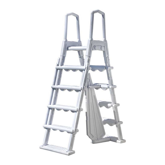
PREMIUM SAFETY LADDER FOR ABOVE GROUND POOL.
EN
Plastic material. Platform included.
ESCALERA PREMIUM de SEGURIDAD PARA PISCINA ELEVADA.
ES
Material plástico. Incluye plataforma.
ÉCHELLE DE SÉCURITÉ SUPÉRIEURE POUR PISCINES HORS SOL.
FR
Matériel plastique. Plateforme incluse.
PREMIUM SICHERHEITSLEITER FÜR AUFSTELLBECKEN.
DE
Kunststoff - Plattform inkl.
SCALETTA CON LIVELLO SICUREZZA PREMIUM PER PISCINE FUORI TERRA.
IT
Realizzata in plastica con piattaforma inclusa.
PREMIUM VEILIGHEIDSLADDER VOOR BOVENGRONDS ZWEMBAD.
NL
Plastic materiaal. Inclusief platform.
ESCADA DE SEGURANÇA SUPERIOR PARA PISCINAS ELEVADAS.
PT
Material plástico. Plataforma incluída.
DRABINA BEZPIECZEŃSTWA PREMIUM DO PODWYŻSZONEGO BASENU.
PO
Tworzywo sztuczne. Zawiera platformę.
Manuel d´instructions - Bedienungsanleitung
Manuale delle instruzioni - Handleiding met instructies
DISTRIBUTED BY / DISTRIBUIDO POR / DISTRIBUÉ PAR / VERTRIEB DURCH / DISTRIBUITO DA / GEDISTRIBUEERD DOOR / DISTRIBUÍDO POR / WYPRODUKOWANY PRZEZ:
MANUFACTURAS GRE, S.A. ARITZ BIDEA Nº 57 BELAKO INDUSTRIALDEA, APARTADO 69 - 48100 MUNGUIA (VIZCAYA) ESPAÑA Nº Reg. Ind. 48-06762
MADE IN CHINA / FABRICADO EN CHINA / FABRIQUÉ AU CHINE / HERGESTELLT IN CHINA / PRODOTTO IN CHINA / GEPRODUCEERD IN CHINA / FABRICADO NA RPC /
Owner´s Manual - Manual de Instrucciones
Manual de instruções
-
Instrukcja obsługi
WYPRODUKOWANO W CHINACH
www.grepool.com
HIML4PL.21
Advertisement
Table of Contents

Related Manuals for GRE SAFETY LADDER


Summary of Contents for GRE SAFETY LADDER
- Page 1 DISTRIBUTED BY / DISTRIBUIDO POR / DISTRIBUÉ PAR / VERTRIEB DURCH / DISTRIBUITO DA / GEDISTRIBUEERD DOOR / DISTRIBUÍDO POR / WYPRODUKOWANY PRZEZ: MANUFACTURAS GRE, S.A. ARITZ BIDEA Nº 57 BELAKO INDUSTRIALDEA, APARTADO 69 - 48100 MUNGUIA (VIZCAYA) ESPAÑA Nº Reg. Ind. 48-06762 MADE IN CHINA / FABRICADO EN CHINA / FABRIQUÉ...
-
Page 2: Content Page
READ THE INSTRUCTION MANUAL CAREFULLY BEFORE ASSEMBLY AND USE. PLEASE ALSO SAVE IT FOR FUTURE REFERENCE. CONTENT PAGE 1- Product introduction 2- Warning and Cautions 3- Assembly and Use Instruction 4- Parameter List 5. Product Explosion Diagram and List of Accesories 1- PRODUCT INTRODUCTION A-Frame ladder adopts blow molding process and polyethylene material, which has strong corrosion resistance feature. - Page 3 Holder Note: The two holders need to be snapped into the groove in the same direction. 3. Install four treads to the holder, see the picture as below. Fix the top tread to the holder by #10x1-1/4 screws. Need to be fi xed by screw Tighten with screws for both right and lift sides 4.
- Page 4 6. Put another bottom tread on a fl at surface with the grooved side facing up; then snap the two holders into the groove. Note: The two holders need to be snapped into the groove in the same direction. Holder 7.
- Page 5 11. Fix the remaining two treads with 10x1-1/4 screws to the holder in the groove positions Install the treads with screws 12. This ladder is designed to fi t multiple pool heights. This ladder is designed to fi t multiple pool heights. Cut line If you pool height is 52 .Locate the fi rst line on the handrail of the ladder.
- Page 6 14. Assemble handrails to the platform, center cover cap opening on side of handrail where platform was just attached. Using a rubber mallet/hammer, tap on cap until the cap is fl ush with handrail. Handrail Cover Cap Deck Plate form 15.
-
Page 7: Parameter List
Bolt Deck Platform Pool Edge Routine Maintenance When the swimming pool is not in use, it is recommended to fl ip the outer ladder upwards, then push it down and fi x it. 1. In winter, the ladder must be removed. 2. - Page 8 47155003 Upper Brace 47155009 Front Barrier 47155010 Back Barrier 47155004 Lower Base 47155007 Left Fixing Strip 47155006 Right Fixing Strip 5862050001 Screw Kit (5´´ Bolt ) 5862050000 Screw Kit (2.5´´ Bolt ) 5862050002 Screw Kit (1-1 / 4´´ Bolt )
-
Page 9: Introducción Al Producto
LEA DETENIDAMENTE EL MANUAL DE INSTRUCCIONES ANTES DEL MONTAJE Y EL USO.GUÁRDELO PARA CONSULTARLO MÁS ADELANTE. ÍNDICE 1. Introducción al producto 2. Advertencias y precauciones 3 3. Instrucciones de montaje y uso 4. Lista de parámetros 7 5. Vista detallada del producto y lista de accesorios 1- INTRODUCCIÓN AL PRODUCTO Esta escalera de tijera se fabrica mediante moldeado por soplado con material de polietileno, que tiene una gran resisten- cia a la corrosión. - Page 10 3- INSTRUCCIONES DE MONTAJE Y USO 1. Extraiga de la caja la escalera de tijera y sus accesorios y compruebe que estén íntegros. 2. En primer lugar, coloque el escalón inferior en una superfi cie plana con la parte acanalada hacia arriba y, a continua- ción, introduzca los pasamanos en las ranuras.
- Page 11 6. Coloque otro escalón inferior en una superfi cie plana con la parte acanalada hacia arriba y, a continuación, introduzca los pasamanos en las ranuras. Nota: Deben introducirse los dos pasamanos en las ranuras en la misma dirección. Pasamanos 7. Fije los escalones a los pasamanos con tornillos n.º 10 × 1-1/4. Fije el escalón al pasamanos con tornillos 8.
- Page 12 11. Fije al pasamanos los dos escalones restantes con tornillos n.º 10 × 1-1/4 en las posiciones de la ranura. Instale los escalones con tornillos. 12. Esta escalera está diseñada para adaptarse a diversas alturas de piscina. Cut line Si la altura de su piscina es 132 cm, localice la primera línea en el pasamanos de la escalera. Con una hoja de sierra, corte uniformemente el pasamanos en ambos lados.
- Page 13 14. Monte las barandillas en la plataforma, centre el tapón de la abertura en el lateral de la barandilla donde se ha aña- dido la plataforma. Con un mazo o martillo de goma, golpee hasta que el tapón se integre en la barandilla. Barandilla Tapón Plataforma...
-
Page 14: Lista De Parámetros
Perno Plataforma Borde de la piscina Mantenimiento rutinario Mantenimiento rutinario Cuando no utilice la piscina, se recomienda elevar la parte exterior de la escalera, presionarla y fi jarla. 1. En invierno debe retirar la escalera. 2. Cuando retire la escalera se recomienda lavarla con agua limpia para eliminar las sustancias químicas de su superfi cie 3. - Page 15 47155009 Barrera frontal 47155010 Barrera posterior 47155004 Base inferior 47155007 Listón de fijación izquierdo 47155006 Listón de fijación derecho 5862050001 Juego de pernos 5 5862050000 Juego de pernos 2,5 5862050002 Juego de pernos 1-1/4 ESCALERA DE SEGURIDAD SUPERIOR PARA PISCINAS ELEVADAS Material plástico.
-
Page 16: Introduction Du Produit
LISEZ ATTENTIVEMENT LA NOTICE AVANT LE MONTAGE ET L’UTILISATION. CONSERVEZ-LA POUR DE FUTURES CONSULTATIONS. SOMMAIRE 1. Introduction du produit 2. Avertissements et précautions 3. Instructions de montage et utilisation 4. Liste de paramètres 5. Vue détaillée du produit et liste d’accessoires 1- INTRODUCTION DU PRODUIT Cette échelle à... - Page 17 2. Placez d’abord la marche inférieure sur une surface plate, la face nervurée vers le haut, puis insérez les rampes dans les fentes. Remarque : les deux mains courantes doivent être insérées dans les fentes dans le même sens. Holder 3.
- Page 18 6. Placez une autre marche inférieure sur une surface plate avec la partie nervurée vers le haut et ensuite, introduisez la rampe dans les fentes. Note : les deux rampes doivent être introduites dans les fentes dans la même direction. Rampe 7.
- Page 19 11. Fixez la rampe aux deux marches restantes avec les vis nº 10 × 1-1/4 dans les positions de la fente. Installez les marches avec des vis 12. Cette échelle est conçue pour être adaptée à différentes hauteurs de piscine. Cette échelle est conçue pour être adaptée à...
- Page 20 14. Montez les mains courantes sur la plateforme, centrez le bouchon d’ouverture sur le côté de la main courante auquel la plateforme a été ajoutée. Avec un marteau en caoutchouc ou un maillet, cognez jusqu’à ce que le bouchon soit intégré...
-
Page 21: Spécification
Boulon Plateforme Bord de la piscine Maintenance de routine Si la piscine n’est pas utilisée, il est conseillé d’élever la partie extérieure de l’échelle, de la placer et la fi xer. Si la piscine n’est pas utilisée, il est conseillé d’élever la partie extérieure de l’échelle, de la placer et la fi xer. 1. - Page 22 47155003 Renfort supérieur 47155009 Barrière frontale 47155010 Barrière postérieure 47155004 Base inférieure 47155007 Baguette de fixation gauche 47155006 Baguette de fixation droite 5862050001 Jeu de boulons 5 5862050000 Jeu de boulons 2,5 5862050002 Jeu de boulons 1-1/4 ÉCHELLE DE SÉCURITÉ SUPÉRIEURE POUR PISCINES HORS SOL Matériel plastique.
-
Page 23: Vorstellung Des Produkts
BEDIENUNGSANLEITUNG VOR ZUSAMMENBAU UND GEBRAUCH BITTE SORGFÄLTIG LESEN UND ZUM SPÄTEREN NACHLESEN AUFBEWAHREN INHALT 1. Vorstellung des Produkts 2. Warn- und Vorsichtshinweise 3. Montage- und Gebrauchsanleitung 4. Tabelle der technischen Eigenschaften 5. Explosionszeichnung Produkt und Liste der Zubehörteile 1- VORSTELLUNG DES PRODUKTS Im Blasformverfahren hergestellte Hochbeckenleiter aus stark korrosionsbeständigem Polyäthylen. - Page 24 beiden Holme durch Einrasten in die Nuten ein. Holm Hinweis: Die beiden Holme müssen gleich ausgerichtet in die Nuten eingesetzt werden 3. Bringen Sie vier Trittfl ächen auf den Holmen an (siehe Abbildung unten). Befestigen Sie obere Trittfl äche mit 10 x 1-1/4 Schrauben.
- Page 25 6. Platzieren Sie eine weitere untere Trittfl äche mit der Nut-Seite nach oben auf eine ebene Fläche und setzen Sie die beiden Holme durch Einrasten in die Nuten ein. Hinweis: Die beiden Holme müssen gleich ausgerichtet in die Nuten eingesetzt werden. Holm 7.
- Page 26 11. Befestigen Sie die beiden restlichen Trittfl ächen mit 10 x 1-1/4 Schrauben in den Nutenpositionen an den Holmen Trittfl ächen mit Schrauben anbringen 12. Die Leiter ist für unterschiedliche Beckenhöhen ausgelegt. 12. Die Leiter ist für unterschiedliche Beckenhöhen ausgelegt. Holme mithilfe Trichter mit Sand füllen Die erste Linie auf dem Handlauf der Leiter entspricht einer Beckenhöhe von 52“.
- Page 27 14. Montieren Sie die Handläufe an der Plattform, wobei die Abdeckkappenöffnung seitlich am Handlauf, an dem zuvor die Plattform angebracht wurde, anzuordnen ist. Klopfen Sie mit einem Gummischläger/Hammer auf die Kappe klopfen, bis die Kappe bündig mit dem Handlauf abschließt. handlauf Abdeckkappe Deckplattform...
- Page 28 Schraube Deckplattform Beckenrand Übliche Wartung Bei Nichtbenutzung des Schwimmbeckens empfi ehlt es sich, die Außenleiter nach oben zu klappen, dann nach unten zu drücken und zu fi xieren. 1. Im Winter muss die Leiter entfernt werden. 2. Um die Leiter von Chemikalien auf der Oberfl äche zu reinigen, sollte sie nach dem Entfernen mit klarem Wasser abgewaschen werden.
- Page 29 47155003 Obere Klammer 47155009 Vordere Sperrschranke 47155010 Hintere Sperrschranke 47155004 Grundplatte 47155007 Linke Befestigungsleiste 47155006 Rechte Befestigungsleiste 5862050001 Schraubenkit 5er Schrauben 5862050000 Schraubenkit 2.5er Schrauben 5862050002 Schraubenkit 1-1 / 4er Schrauben HOCHWERTIGE SICHERHEITSLEITER FÜR AUFSTELLBECKEN. Aus Kunststoff. Mit Plattform...
-
Page 30: Introduzione Al Prodotto
DI ISTRUZIONI PRIMA DELL’ASSEMBLAGGIO E DELL’UTILIZZO. CONSERVARLO PER RIFERIMENTI CONTENUTO 1. Prodotto Introduzione 2. Avvertenze e precauzioni 3. Assemblaggio e istruzioni di utilizzo 4. Elenco parametr 5. Diagramma con vista esplosa del prodotto ed elenco accessori 1- INTRODUZIONE AL PRODOTTO La scala con telaio ad A è... - Page 31 3- ASSEMBLAGGIO E ISTRUZIONI PER L’USO 1. Rimuovere la scala con telaio ad A e i suoi accessori dalla scatola e controllare se tutti gli accessori sono completi. 2. Per prima cosa posizionare il gradino inferiore su una superfi cie piana con il lato scanalato rivolto verso l’alto; quindi agganciare i due supporti nella scanalatura;...
- Page 32 6. Posizionare un altro gradino inferiore su una superfi cie piana con il lato scanalato rivolto verso l’alto; quindi aggan- ciare i due supporti nella scanalatura. Nota: I due supporti devono essere inseriti nella scanalatura nella stessa direzione Titolare 7. Fissare i gradini ai supporti con le viti con # 10x1-1 / 4. Fissare i gradini ai supporti con le viti con # 10x1-1 / 4.
- Page 33 11. Fissare i restanti due gradini con viti 10x1-1 / 4 al supporto nelle posizioni delle scanalature Installare i gradini con le viti 12. Questa scala è progettata per adattarsi a più altezze di piscine. Cut line Se l’altezza della piscina è 52 (132cm), posizionare la prima linea sul corrimano della scala. Utilizzando un seghetto, ta- gliare il corrimano in modo uniforme su entrambi i lati Se l’altezza della piscina è...
- Page 34 14. Montare i corrimano sulla piattaforma, aprendo il tappo di copertura centrale sul lato del corrimano dove la piatta- forma era stata appena fi ssata. Utilizzando un martello / mazzuolo in gomma, picchiettare sul tappo fi no a quando il tappo è...
- Page 35 Utilizzare il bullone da 5 del kit viti 5862050001! se l’altezza della piscina è 54 (137) Bullone Piattaforma del ponte Bordo piscina Manutenzione ordinaria Quando la piscina non è in uso, si consiglia di ribaltare la scala esterna verso l’alto, quindi spingerla verso il basso e Quando la piscina non è...
- Page 36 47155005 Supporto 47155002 Gradino 47155008 Gradino inferiore 47155003 Sostegno superiore 47155009 Barriera anteriore 47155010 Barriera posteriore 47155004 Base inferiore 47155007 Striscia di fissaggio sinistra 47155006 Striscia di fissaggio destra 5862050001 Kit viti bullone da 5"! 5862050000 Kit viti bullone da 2,5"! 5862050002 Bullone da 1-1/4"...
- Page 37 LEES VÓÓR MONTAGE EN GEBRUIK DE GEBRUIKSAANWIJZING ZORGVULDIG DOOR. BEWAAR DEZE GEBRUIKSAANWIJZING ALS NASLAGWERK VOOR IN DE TOEKOMST. INHOUD 1. Kennismaking met het product. 2. Waarschuwing en voorzorgsmaatregelen. 3. Montage- en gebruiksinstructie 4. Parameterlijst 5. Product Explosiediagram en Lijst van Accessoires 1- KENNISMAKING MET HET PRODUCT Voor de A-frameladder is gebruikgemaakt van een blaasvormproces met polyethyleen, een materiaal dat sterke anticor- rosieve eigenschappen heeft.
- Page 38 1. Haal de A-frameladder en bijbehorende accessoires uit de doos en controleer of alle accessoires compleet zijn. Plaats eerst de onderste trede op een vlakke ondergrond met de gegleufde zijde naar boven; klik vervolgens de twee houders in de sleuf; 2.
- Page 39 6. Leg de andere onderste trede op een vlakke ondergrond met de gegroefde zijde naar boven; klik vervolgens de twee houders in de sleuf. Let op: De twee houders moeten in dezelfde richting in de sleuf worden geklikt. Houder 7. Zet de treden met #10x1-1 / 4-schroeven vast aan de houders. Zet de treden met #10x1-1 / 4-schroeven vast aan de houders.
- Page 40 11. Zet de laatste twee treden met 10x1-1/4-schroeven vast aan de houder op de plaatsen in de sleuven. Installeer de treden met schroeven 12. 12. Deze ladder is ontworpen voor meerdere zwembadhoogtes. 12. Deze ladder is ontworpen voor meerdere zwembadhoogtes. Zaaglijn Als de hoogte van het zwembad 52 is: Zoek de eerste lijn op de handrail van de ladder.
- Page 41 14. Monteer de leuningen aan het platform, centreer de opening van de afdekkap aan de kant van de leuning waar hij net is bevestigd aan het platform. Gebruik een rubberen klopper/hamer en klop op de dop totdat de dop gelijk ligt met de handrail.
- Page 42 Bout Deckplatform Zwembadrand Routine-onderhoud Als het zwembad niet in gebruik is, wordt aanbevolen om de buitenste ladder naar boven te klappen en vervolgens naar beneden te duwen en vast te zetten. beneden te duwen en vast te zetten. 1. In de winter moet de ladder worden verwijderd. 2.
- Page 43 47155008 Onderste trede 47155003 Bovenste klembeugel 47155009 Voorste barrière 47155010 Achterste barrière 47155004 Onderstel 47155007 Linker bevestigingsstrook 47155006 Rechter bevestigingsstrook 5862050001 Schroefkit 5%bout! 5862050000 Schroefkit 2,5%bout! 5862050002 Schroefkit 1-1 /45%bout! PREMIUM VEILIGHEIDSLADDER VOOR BOVENGRONDS ZWEMBAD. Plastic materiaal. Inclusief platform.
-
Page 44: Introdução Ao Produto
LEIA ATENTAMENTE ESTE MANUAL DE INSTRUÇÕES ANTES DE PROCEDER À MONTAGEM E DE UTILIZAR A ESCADA. GUARDE ESTE MANUAL PARA FUTURAS CONSULTAS. ÍNDICE 1. Introdução ao produto 2. Advertências e precauções 3. Instruções de montagem e utilização 4. Lista de parâmetros 5. - Page 45 2. Em primeiro lugar, coloque o degrau inferior numa superfície plana com a parte acanalada para cima, e em seguida introduza os corrimões nas ranhuras. Corrimões Nota: Os dois corrimões devem introduzir-se nas ranhuras na mesma direção.. 3. Acople os quatro degraus aos corrimões como indica a seguinte fi gura. Fixe o degrau superior aos corrimões com os parafusos N.º...
- Page 46 6. Coloque outro degrau inferior numa superfície plana, com a parte acanalada virada para cima, e introduza os cor- rimões nas ranhuras. Nota: Os dois corrimões devem introduzir-se nas ranhuras na mesma direção. Corrimões 7. Fixe os degraus aos corrimões com os parafusos n.º 10 × 1-1/4. Fixe os degraus aos corrimões com os parafusos n.º...
- Page 47 11. Fixe os degraus restantes aos corrimões com parafusos n.º 10 × 1-1/4 nas posições da ranhura. Instale os degraus com parafusos. 12. Esta escada foi concebida para se adaptar a diferentes alturas de piscinas. Esta escada foi concebida para se adaptar a diferentes alturas de piscinas. Linha de corte Se a altura da sua piscina for de 132 cm, localize a primeira linha nos corrimões da escada.
- Page 48 14. Monte as balaustradas na plataforma, centre o tampão da abertura na parte lateral da balaustrada onde se acrescen- tou a plataforma. Com a ajuda de um maço ou de um martelo de borracha, golpeie até que o tampão fi que completa- mente nivelado com a balaustrada.
-
Page 49: Lista De Parâmetros
Perno Plataforma Borda da piscina Manutenção de rotina Quando não utilizar a piscina, é recomendável elevar a parte exterior da escada, pressionando-a e fi xando-a na posição elevada. 1. Retire a escada da piscina durante o inverno. 2. Quando retirar a escada, é recomendável lavá-la com água limpa, para eliminar as substâncias químicas que possam aderir-se à... - Page 50 47155008 Degrau inferior 47155003 Reforço superior 47155009 Barreira frontal 47155010 Barreira posterior 47155004 Base inferior 47155007 Travessa de fixação esquerda 47155006 Travessa de fixação direita 5862050001 Conjunto de pernos 5 5862050000 Conjunto de pernos 2,5 5862050002 Conjunto de pernos 1-1/4...
- Page 51 NALEŻY OSTROŻNIE PRZECZYTAĆ NINIESZĄ INSTRUKCJĘ OBSŁUGI PRZED PRZYSTĄPIENIEM DO MONTAŻU ORAZ UŻYTKOWANIA. NALEŻY ZACHOWAĆ NINIEJSZĄ INSTRUCJĘ OBSŁUGI NA PRZYSZŁY UŻYTEK. ZAWARTOŚĆ STRONY 1. Informacje o produkcie 2. Ostrzeżenia i uwagi 3. Montaż oraz użytkowanie 4. Parametry 5. Schemat produktu i jego elementy składowe 1- INFORMACJE O PRODUKCIE 6.
- Page 52 3- MONTAŻ ORAZ UŻYTKOWANIE 1. Należy rozpakować drabinę ramową oraz jej element z pudełka i sprawdzić, czy wszystkie akcesoria są kompletne. 2. W pierwszej klojności należy umieścić dolny bieżnik na płaskiej powierzchni, stroną z rowkiem skierowaną do góry, a następnie zatrzasnąć dwa uchwyty w rowku; Blokada Uwaga: Oba uchwyty muszą...
- Page 53 6. Następnie należy umieścić kolejny dolny element antypoślizgowy na stopniu, tak aby bardziej chropowata część wraz z rowkiem była skierowana do góry, następnie należy zatrzasnąć dwa uchwyty w rowku. Uwaga: Obie szyny należy zatrzasnąć w rowku w tym samym kierunku. Blokada 7.
- Page 54 11. Należy przymocować pozostałe dwa elementy antypośligowe za pomocą śrub # 10x1-1/4 do uchwytu w rowkach. Należv zamontować elementy anty- poślizgowe za pomocą śrub Niniejsza drabina została zaprojektowana tak, aby pasowała do wielu wysokości basenów. Jeśli wysokość basenu to 52, należy wsunąć...
- Page 55 14. Należy zamontować 2 poręcze do górnej podstawy, montując stopień w środkowe otwory znajdujące się na boku poręczy. Za pomocą gumowego młotka należy wbić zaślepkę tak aby była równo z poręczą. Poręcz Zaślepki Górny stopień 15. Należy przymocować poręcze, wsuwając je w poręcze. 16.
- Page 56 Śruby Górny stopień Kraweędż basenu Rutynowa konserwacja Gdy basen nie jest używany, zaleca się obrócić drabinkę zewnętrzną do góry, a następnie zablokować ją w dół i przy- Gdy basen nie jest używany, zaleca się obrócić drabinkę zewnętrzną do góry, a następnie zablokować ją w dół i przy- mocować.
- Page 57 47155003 Przedni element drabiny 47155009 Tylny element drabiny 47155010 Dolna podstawa 47155004 Lewa szyna mocująca 47155007 Prawa szyna mocująca Zestaw śrub 5" nakrętki 47155006 Zestaw śrub 2.5" nakrętki 5862050001 Zestaw śrub 1-1 / 4" nakrętki 5862050000 Screw Kit (1-1 / 4´´ Bolt ) 5862050002...
-
Page 58: General Terms
1- GENERAL TERMS In accordance with these provisions, the seller guarantees that the product corresponding to this guarantee (“the • Product”) is in perfect condition at the time of delivery. The Guarantee Term for the Product is two (2) years from the time it is delivered to the purchaser. •... -
Page 59: Aspectos Generales
1- ASPECTOS GENERALES De acuerdo con estas disposiciones, el vendedor garantiza que el producto correspondiente a esta garantía (“el • Producto”) no presenta ninguna falta de conformidad en el momento de su entrega. El Período de Garantía para el Producto es de dos (2) años y se calculará desde el momento de su entrega al comprador. •... -
Page 60: Aspects Généraux
1- ASPECTS GÉNÉRAUX Conformément à ces dispositions, le vendeur garantit que le produit correspondant à cette garantie (“le Produit”) ne • présente aucun défaut de conformité à la date de sa livraison. La Période de Garantie pour le Produit est de deux (2) ans et elle sera calculée à partir du moment de sa remise à •... - Page 61 1- ALLGEMEINE GESICHTSPUNKTE In Übereinstimmung mit diesen Verfügungen garantiert der Verkäufer, dass das Produkt dieser Garantie (“das Produkt”) • entspricht und dass es im Moment der Übergabe in allen Punkten mit den Anforderungen übereinstimmt. Der Garantiezeitraum für das Produkt beträgt zwei (2) Jahre und wird ab dem Augenblick der Lieferung an den Käufer •...
-
Page 62: Aspetti Generali
1- ASPETTI GENERALI Ai sensi delle seguenti disposizioni, il venditore garantisce che il prodotto corrispondente a questa garanzia (“il • Prodotto”) non presenta alcun difetto di conformità al momento della sua consegna. Il Periodo di Garanzia per il Prodotto è di due (2) anni a decorrere dal momento della consegna dello stesso all’acquirente. •... - Page 63 1- ALGEMENE ASPEKTEN In overeenkomst met de voorliggende bepalingen wordt door de verkoper gegarandeerd dat het produkt verkocht • onder deze garantie (“het Produkt”) geen enkel defekt vertoont op het moment van levering. De Garantieperiode voor het Produkt bedraagt twee (2) jaar en is geldig vanaf het moment dat het Produkt aan de •...
-
Page 64: Condições Gerais
1- CONDIÇÕES GERAIS De acordo com estas disposições, o vendedor garante que, no momento da entrega, o produto correspondente a esta • garantia (“o Produto”) não apresenta nenhum tipo de falta de conformidade. O Período de Garantia para o Produto é de dois (2) anos, contados a partir da data de entrega ao comprador. •... -
Page 65: Warunki Ogólne
1- WARUNKI OGÓLNE Zgodnie z tymi postanowieniami sprzedawca gwarantuje, że produkt odpowiadający tej gwarancji («Produkt») jest w • idealnym stanie w momencie dostawy. Okres gwarancji na produkt wynosi dwa (2) lata od momentu dostarczenia go nabywcy. • W przypadku jakiejkolwiek wady Produktu, o której Kupujący poinformował sprzedającego w okresie Gwarancji, •... - Page 66 If You Have Any Problem, Contact Us! www.grepool.com/en/after-sales Si Tienes Algun Problema, ¡Consultenos! España www.grepool.com/post-venta France/ En Cas De Probleme, Nous Consulter! www.grepool.com/fr/apres-vente Belgie Sollten Sie Probleme Haben, Zögern Sie Bitte Deutschland www.grepool.com/de/kundenservice Nicht, Uns Zu Kontaktieren! Per Ogni Vostra Eventualle Occorrenza, Italia www.grepool.com/it/post-vendita Interpellateci!
Need help?
Do you have a question about the SAFETY LADDER and is the answer not in the manual?
Questions and answers