Table of Contents
Advertisement
Quick Links
Advertisement
Table of Contents

Subscribe to Our Youtube Channel
Summary of Contents for Flintec FAA-26
- Page 1 FAA-26 Analogue Amplifier Technichal Manual www.flintec.com...
-
Page 2: Table Of Contents
Adjustments ................... 11 5.1 Adjustment with rotary switch ............11 5.2 Adjustment at PLC ..............12 5.3 Testing the Scale Performance ........... 12 Operation ..................13 Trouble Shootıng ................14 FAA-26, Technical Manual, Rev. 1.2.0, December 2020 Page 2 of 14... -
Page 3: Safety Instructions
FLINTEC operating and maintenance instructions. FLINTEC shall not be liable against any damages or problems arising from the use of any options or any consumable products other than those designated as Original FLINTEC Products. -
Page 4: Declaration Of Conformity
2. Declaration of Conformity FAA-26, Technical Manual, Rev. 1.2.0, December 2020 Page 4 of 14... -
Page 5: Front View, Features And Specifications
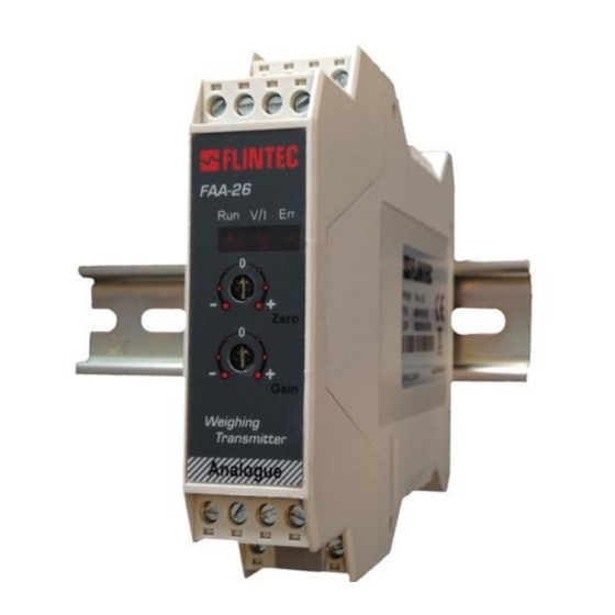
Front View, Features and Specifications Microcontroller based analogue load cell transmitter FAA-26 has very high accuracy and long-term stability with its state-of-the-art design. This high accurate instrument gives the system designers a lot of advantages to increase the system reliability and to reduce the installation and service times. All instruments’... - Page 6 Operation Temperature Between -10 °C and +45 °C at 85% RH max, non-condensing EMC Immunity Class E2 Enclosure Polyamide, for DIN-rail mount, IP20 Dimensions Front Width:22,5 mm, Front Length: 99 mm , Height:114,5mm, FAA-26, Technical Manual, Rev. 1.2.0, December 2020 Page 6 of 14...
-
Page 7: Installation And Commissioning
FAA-26 instruments are very low-level signal measuring instruments. To avoid electrical noise, FAA-26 should be separated from the equipments that produce electrical noise. Preferable use metal cabinet against radio frequency interference and the cabinet shall be connected to ground against the electromagnetic disturbances. -
Page 8: Mechanical Installation
The input resistance of the load cells that you want to connect should be more than 85 Ω. Pin Name Load Cell Cable + Excitation - Excitation + Signal - Signal Shield FAA-26, Technical Manual, Rev. 1.2.0, December 2020 Page 8 of 14... -
Page 9: Analogueue Output Connection
Voltage output connection 4.4 Changing of the Analogue Output Type FAA-26 checks the T and R pins connection and sets its analogue output according to the table below at power on. To change the analogue output mode short circuit or open circuit T and R pins of the instrument before power on the instrument. -
Page 10: Commissioning
• The analogue output cabling should be done for the same analogue output type. • The adjustment rotary switches shall be at “ 0 “ position at power on. FAA-26, Technical Manual, Rev. 1.2.0, December 2020 Page 10 of 14... -
Page 11: Adjustments
The zero adjustment rotary switch should be at “0“ position at the end of the adjustment. Gain Adjustment Connect the measurement instrument to the analogue output. Load the scale. The analogue output value should be calculated for the applied load. FAA-26, Technical Manual, Rev. 1.2.0, December 2020 Page 11 of 14... -
Page 12: Adjustment At Plc
4 – 20 mA output range, the output will be 4 mA at 0 mV load cell signal (scale empty) and will be 20 mA at 10 mV load cell signal (max. scale capacity). Changing the FAA-26 instrument the re-calibration is not required because of matching instruments in production at Flintec. -
Page 13: Operation
6. Operation There are 3 LEDs and 2 adjustment rotary switches on the front panel of FAA-26. The rotary switches should be at “0“ positions for operation. In operation rotary switch positions, T and R pins connection, and LEDs announces are:... -
Page 14: Trouble Shootıng
7. Trouble Shooting The type FAA-26 amplifier was designed as a very reliable and virtually error free instrument. However, if an error occurs, do not attempt to repair the equipment before you understand what caused the error. Note the status of the front panel LEDs and try to find the problem with the help of the table given below.


Need help?
Do you have a question about the FAA-26 and is the answer not in the manual?
Questions and answers