
Related Manuals for Flintec FAA-27


Summary of Contents for Flintec FAA-27
- Page 1 Analog Amplifier FAA-27 Technical Manual Flintec GmbH Bemannsbruch 9 74909 Meckesheim GERMANY www.flintec.com...
-
Page 2: Table Of Contents
Operation ..................18 Programming With xFace Software Over RS232 ......19 8.1 Installation Of xFace Software ............ 19 8.2 Connection To The xFace Software ..........19 Trouble Shooting ................21 FAA-27, Technical Manual, Rev. 1.1, June 2014 Page 1 of 21... -
Page 3: Safety Instructions
FLINTEC reserves the right to revise this manual and alter its content without notification at any time. Neither FLINTEC nor its affiliates shall be liable to the purchaser of this product or third parties for damages, losses, costs, or expenses incurred by purchaser or third parties as a result of: accident, misuse, or abuse of this product or unauthorized modifications, repairs, or alterations to this product, or failure to strictly comply with FLINTEC operating and maintenance instructions. -
Page 4: Declaration Of Conformity
2. Declaration of Conformity FAA-27, Technical Manual, Rev. 1.1, June 2014 Page 3 of 21... -
Page 5: Front View, Features And Specifications
SERIAL CONNECTION TxD ( RS232C ) RxD ( RS232C ) Ground ( RS232C ) SETPOINT CONNECTION Digital Output 1 Digital Output 2 Digital Outputs Common POWER SUPPLY +24VDC 0VDC FAA-27, Technical Manual, Rev. 1.1, June 2014 Page 4 of 21... - Page 6 Calibration at PLC does not require readjustment after changing instrument because of matching in the production. 2 pcs free relay contact output for alarm or controlling valves, gate etc. FAA-27, Technical Manual, Rev. 1.1, June 2014 Page 5 of 21...
- Page 7 Operation Temperature Between -10°C and +45°C at 85% RH max, non-condensing EMC Immunity Class E2 Enclosure Polyamide, for DIN-rail mount, IP20 Dimensions Front Width:22,5 mm, Front Length: 99 mm , Height:114,5mm FAA-27, Technical Manual, Rev. 1.1, June 2014 Page 6 of 21...
-
Page 8: Installation And Commissioning
All external cables should be installed safely to avoid mechanical damages. FAA-27 instruments are very low level signal measuring instruments. To avoid electrical noise, FAA-27 should be separated from the equipments that produce electrical noise. Preferable use metal cabinet against radio frequency interference and the cabinet shall be connected to ground against the electromagnetic disturbances. -
Page 9: Mechanical Installation
Only one of the analog output types can be used at the same time and has to be selected in the setup type. Install the analog output measuring instrument for adjustment, if need be. FAA-27, Technical Manual, Rev. 1.1, June 2014 Page 8 of 21... -
Page 10: Changing The Analogue Output
Voltage output connection Changing the Analogue Output FAA-27 sets its analog output according to the table below at power on. Turn the programming switch and connect TxD and RxD pins as indicated in the table below before power on the instrument to set analog output type and its signal level. -
Page 11: Serial Port Connection
Check the analogue output set up described in chapter 4.4. The analogue output cabling should be done for the same analogue output type. The adjustment (Adj) rotary switch shall be at “0“ - position. FAA-27, Technical Manual, Rev. 1.1, June 2014 Page 10 of 21... -
Page 12: Adjustments
G position to start gain adjustment. Gain Adjustment Connect the measurement instrument to the analog output. Load the scale. The analog output value should be calculated for the applied load. FAA-27, Technical Manual, Rev. 1.1, June 2014 Page 11 of 21... - Page 13 The instrument saves 4 different adjustments in its memory for the voltage and current outputs and their ranges. Changing the analog output type it automatically set the adjustment to the output range used before. FAA-27, Technical Manual, Rev. 1.1, June 2014 Page 12 of 21...
-
Page 14: Fast Adjustment To Nominal Output Range
Due to the production process of FAA-27, eCal accuracy is very high. Adjustment with eCal is performed via RS232 port of the instrument and can be comfortable executed with xFace software. -
Page 15: Adjustment (Ecal) With Plc
FAA-27 can be electronically calibrated via RS232C serial interface by commands or by xFace software. If you want to use your own software to calibrate the FAA-27 from your PLC or PC, you may use the commands below. The yellow colored bytes are the data in the command and blue colored bytes are check sum in this document. - Page 16 Stop the eCal process Response: @011000000001EE 3. Digital Filter Setting: Command: @011000220001020000CA Set the Fast filter Command: @011000220001020001C9 Set to Medium filter Command: @011000220001020002C8 Set to Slow filter Response: @011000220001CC FAA-27, Technical Manual, Rev. 1.1, June 2014 Page 15 of 21...
-
Page 17: Testing The Scale Performance
Testing the Scale Performance You have to check the scale performance by testing the scale eccentricity, scale linearity at loading up to maximum loading value, repeatability etc. before using it. FAA-27, Technical Manual, Rev. 1.1, June 2014 Page 16 of 21... -
Page 18: Setpoints
6. Setpoints Setpoint Connection FAA-27 has 2 free relay contact output. These outputs can be connected to maximum 230VAC or maximum 30VDC, maximum 1A loads. Reverse diode connection to the DC loads is recommended to increase the relay contact life and to reduce the disturbances. -
Page 19: Operation
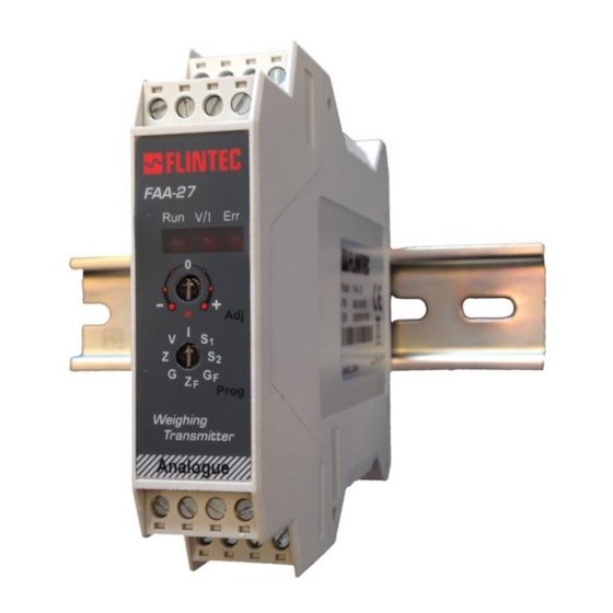
7. Operation There are 3 LEDs and 2 rotary switches on the front panel of FAA-27. The rotary switches are being used for adjustment as described in chapter 4.4 and the LEDs have different meanings in operation and setup type as indicated below. -
Page 20: Programming With Xface Software Over Rs232
8. Programming With xFace Software Over RS232 FAA-27 has RS232C serial interface to perform eCal electronic calibration and to adjust filter, setpoint values and to follow status by using xFace software installed on a PC. For installing the xFace software, which is supplied with the instrument or can be downloaded from www.flintec.com, follow the steps described below. - Page 21 After performing eCal as described in the software, check the performance of your system. You may adjust to instrument to factory default by xFace, if it is changed before. FAA-27, Technical Manual, Rev. 1.1, June 2014 Page 20 of 21...
-
Page 22: Trouble Shooting
9. Trouble Shooting The type FAA-27 amplifier is designed as a very reliable and virtually error free instrument. However, if an error occurs, do not attempt to repair the equipment before you understand what caused the error. Note the status of the front panel LEDs, and try to find the problem with the help of the table given below.
Need help?
Do you have a question about the FAA-27 and is the answer not in the manual?
Questions and answers