
Related Manuals for Metreel MET-TRACK

Summary of Contents for Metreel MET-TRACK
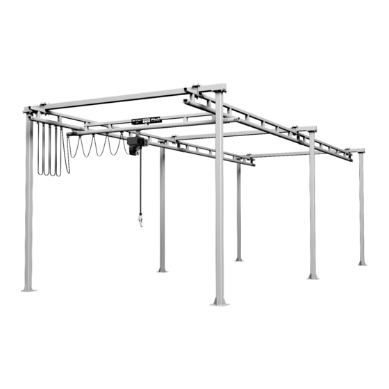
- Page 1 MET-TRACK ® Workstation Bridge Cranes FLOOR MOUNTED Installation & Maintenance Instructions TOLL Free Tel: Email: Website: 877-830-9803 sales@metreel.com www.metreel.com...
-
Page 2: Table Of Contents
Floor Mounted Workstation Bridge Crane Installation & Maintenance Instructions CONTENTS Introduction ............................3 Preparation ............................. 3 Column and Header Installation ......................4-5 Runway Installation ..........................6-8 Bridge & End Truck Options and Parts Breakdown ................9-17 Hoist Trolley and Bridge Festoon Installation ..................18 Festoon Storage Extensions (FSE) ...................... -
Page 3: Introduction
75lb. There is also an allowance with the design for normal impact loading caused by the bridge and hoist movement. To ensure that you continue to get many years of service from the MET-TRACK Workstation Crane we ®... -
Page 4: Column And Header Installation
Floor Mounted Workstation Bridge Crane Installation & Maintenance Instructions COLUMN & HEADER INSTALLATION 1) Layout and mark the area where the crane is to be installed (refer to the General Arrangement Drawing for dimensions) 2) Mark out the floor BEFORE drilling using the column bas plate as a template (or refer to the General Arrangement Drawing for dimensions). - Page 5 Floor Mounted Workstation Bridge Crane Installation & Maintenance Instructions 6) Follow the same procedure for the remaining column and header sets Fixings Parts List Column to Header Beam (per column) 5/8” x 2” Bolt 5/8” Nut Type B ‘Narrow’ 5/8” Washer Regular 5/8”...
-
Page 6: Runway Installation
Floor Mounted Workstation Bridge Crane Installation & Maintenance Instructions RUNWAY INSTALLATION 1) As the runway sections maybe different depending upon your span selection, check the General Arrangement Drawing to identify individual gantry sections 2) Being careful not to disturb the columns, lift the first set of runway sections into place (refer to the General Arrangement Drawing for position and dimension details) 3) Using the runway fixing brackets secure the runway to the header (see fig 5) Fixings Parts List... - Page 7 Floor Mounted Workstation Bridge Crane Installation & Maintenance Instructions 7) Torque fasteners to 75ft.-lb and ensure at least two treads are visible after tightening 8) If you have no more runways to install then skip to step 16 9) Install Joint Kits to previously installed runway (See fig 6) Fixings Parts List Track Joints (per Joints) ½”...
- Page 8 Floor Mounted Workstation Bridge Crane Installation & Maintenance Instructions 12) Align the runway profile so that the running surfaces are level a) To adjust for smooth travel, use the bolts on the top of the splice joint to force the track down into the base of the splice joint.
-
Page 9: Bridge & End Truck Options And Parts Breakdown
Floor Mounted Workstation Bridge Crane Installation & Maintenance Instructions BRIDGE & END TRUCK OPTIONS AND PARTS BREAKDOWN Please ensure you have the correct End Truck Standard End Truck Part No. 1454 1554 1654 1754 Cap.(lbs) 1000 2000 Bridge Length Upto 23ft 1454L End Truck Description Part No. - Page 10 Floor Mounted Workstation Bridge Crane Installation & Maintenance Instructions 1654L End Truck Description Part No. 600 Series Splice Plate Weldment 23620 SHS for 600 Series Extended Trolley 23624 Trolley for 600 Series Extended Truck 23607 Plastic End Cap GPN 260 Q 5050 5 End Truck Fixing Kit 3 28036 1754L End Truck...
- Page 11 Floor Mounted Workstation Bridge Crane Installation & Maintenance Instructions 1554-400 End Truck Description Part No. 400 Series Splice Plate Weldment 23618 Packer Plates for End Truck Designs 23629 Plastic End Cap GPN 260 Q 5050 5 Trolley for 500 Series Extended End Truck 23623 SHS for 1554-400 &...
- Page 12 Floor Mounted Workstation Bridge Crane Installation & Maintenance Instructions 1654-500 End Truck Description Part No. 500 Series Splice Plate Weldment 23621 Packer Plates for End Truck Designs 23629 Plastic End Cap GPN 260 Q 5050 5 600 Series Extended End Truck 23624 SHS for 1654-400 &...
- Page 13 Floor Mounted Workstation Bridge Crane Installation & Maintenance Instructions 1554L-500 End Truck Description Part No. 400 Series Splice Plate Weldment 23618 Packer Plates for End Truck Designs 23629 Plastic End Cap GPN 260 Q5050 5 Trolley for 600 Series Extended End Truck 23623 SHS for 1654-400 &...
- Page 14 Floor Mounted Workstation Bridge Crane Installation & Maintenance Instructions 1654L-500 End Truck Description Part No. 500 Series Splice Plate Weldment 23619 Packer Plates for End Truck Designs 23629 Plastic End Cap GPN 260 Q5050 5 600 Series End Truck 23624 SHS for 600 Series Extended Trolley 23607 End Truck Fixing Kit 3...
- Page 15 Floor Mounted Workstation Bridge Crane Installation & Maintenance Instructions 1854 End Truck Description Part No. 700/850 Series Splice Plate Weldment 23621 Trolley for 800 Series Extended End Truck 23626 Plastic End Cap GPN 260 Q5050 5 SHS for 1854 End Truck 28033 End Truck Fixing Kit 4 28037...
- Page 16 Floor Mounted Workstation Bridge Crane Installation & Maintenance Instructions 1) If a festoon system has been selected for this workstation crane then it may be necessary to put the appropriate number of festoon trolleys, end clamps and festoon storage extension (FSE) on to one of the runway’s prior to the bridge being installed.
- Page 17 Floor Mounted Workstation Bridge Crane Installation & Maintenance Instructions Fixings Parts List End Stop Kits All fixings must be UNC All fixings must be SAE Grade 5 400 Series 500 Series 600 Series 700 / 800 Series 1 x RB45 Sleeve 1 x RB45 Sleeve 1 x RB67 Sleeve 1 x RB67 Sleeve...
-
Page 18: Hoist Trolley And Bridge Festoon Installation
Floor Mounted Workstation Bridge Crane Installation & Maintenance Instructions HOIST TROLLEY AND BRIDGE FESTOON INSTALLATION Install hoist trolley and festoon trolleys on crane bridge track, if applicable, as shown in fig 12. Secure End Stop bolts and rubber bumpers, also shown in fig 12. Install the festoon cable/hose on the festoon trolleys at equal spacing, ensure festoon has correct loop depth (refer to the General Arrangement Drawing). -
Page 19: Festoon Storage Extensions (Fse)
Floor Mounted Workstation Bridge Crane Installation & Maintenance Instructions FESTOON STORAGE EXTENSIONS (FSE) 400 Series Festoon Extension (Must be welded to the runway – refer to the General Arrangement Drawing) 500 Series Festoon Extension 600 Series Festoon Extension Page 19 of 29 Document No. -
Page 20: Hoist Trolley Installation
Floor Mounted Workstation Bridge Crane Installation & Maintenance Instructions 700 & 800 Series Festoon Extension HOIST AND TROLLEY INSTALLATION Attach hoist to hoist trolley. Use washers on host mounting pin to centre hoist inside hoist trolley. Reinstall washer on outside of hoist trolley before installing or reinstalling cotter pin to secure hoist mounting pin. Replace cotter pin if worn or broken. -
Page 21: Service Connections
Keep Packing List, Installation Manual, General Arrangement Drawing and any other documents filed together in a safe place WARNING, SAFETY AND CAPACITY LABELS If at any time these labels are lost, stolen, removed or become illegible please contact Metreel at sales@metreel.com for replacements. LOAD TESTING After the MET-TRACK ®... -
Page 22: Sway Bracing (Optional)
It should be noted that the use of sway bracing is purely subjective because it is not a requirement of Metreel, Inc. No specifications exist detailing appropriate methods and the ultimate quantity and type is at the discretion of the user and installer. -
Page 23: Operator Instructions
MET-TRACK ® operator to be fully trained in the use of the MET-TRACK ® system and be The hoist hook can then be raised very slowly in order to fully aware of both the danger to life and or serious injury remove slack from the hoist slings or chain. - Page 24 MET-TRACK ® is to remain isolated. injury to personnel or overloading the MET-TRACK ® 14) The hoist trolley should not contact the bridge stop NEVER attempt to lift loads outside the standard lift bolts and buffers under normal operating conditions.
-
Page 25: Inspection And Maintenance Schedule
Floor Mounted Workstation Bridge Crane Installation & Maintenance Instructions INSPECTION AND MAINTENANCE SCHEDULE The information below covers suggested inspection procedure of a MET-TRACK ® system in order to guarantee trouble free operation and running. It is strongly recommended to check all of the criteria listed below one month after the initial installation of the system to ensure that all fixings are correctly tightened after the system has settled following installations. - Page 26 Floor Mounted Workstation Bridge Crane Installation & Maintenance Instructions FESTOON STORAGE EXTENSION TO RUNWAY TRACK HARDWARE (if fitted) Frequency: Every 12 Months Maintenance Ensure bolts are tightened to Procedure: manufacturers specified torque value. (refer to installation manual for details) Ensure that the two screw on the top of extension are correctly adjusted to provide a flush rolling surface from the runway to storage extension.
- Page 27 Floor Mounted Workstation Bridge Crane Installation & Maintenance Instructions HOIST TROLLEY Frequency: Every 12 Months Maintenance Ensure that the cotter pin is Procedure: wrapped securely around the load pin. Perform visual check for any signs of damage to cotter pin. Perform visual check for any signs of damage to load pin.
- Page 28 Floor Mounted Workstation Bridge Crane Installation & Maintenance Instructions BRIDGE END TRUCKS - STANDARD Frequency: Every 12 Months Maintenance Check that the bridge has the Procedure: correct 12” cantilever from the end of the bridge to the centre line of the end truck.
-
Page 29: Warranty Statement
Or any combination of the above which, in the opinion of Metreel Inc. shall be reasonable • Provided that Metreel Inc.’s liability shall in no event exceed the price of the Goods or Services and performance of any of the above options shall constitute an entire discharge of Metreel Inc.’s liability under this warranty.
Need help?
Do you have a question about the MET-TRACK and is the answer not in the manual?
Questions and answers