YOKOGAWA CENTUM CS 3000 Installation Guidance
Hide thumbs
Also See for CENTUM CS 3000:
- Technical information (254 pages) ,
- Technical information (188 pages)
Table of Contents
Advertisement
Advertisement
Table of Contents

Related Manuals for YOKOGAWA CENTUM CS 3000


Summary of Contents for YOKOGAWA CENTUM CS 3000
- Page 1 Technical CENTUM CS 3000 Installation Guidance Information TI 33Q01J10-01E Yokogawa Electric Corporation TI 33Q01J10-01E 2-9-32, Nakacho, Musashino-shi, Tokyo, 180-8750 Japan ©Copyright May 1998 (YK) Tel.: 81-422-52-5634 Fax.: 81-422-52-9802 13th Edition Feb. 2009 (YK)
- Page 2 Blank Page...
- Page 3 Introduction The CENTUM CS 3000 (abbreviated as CS 3000) is a distributed control system (abbreviated as DCS) for small to large plants. This manual describes the requirements for installation (control room size and power supply requirements), storage and transportation, and wiring.
- Page 4 • If any protection or safety circuit is required for the system controlled by the product or for the product itself, prepare it separately. • Be sure to use the spare parts approved by Yokogawa Electric Corporation (hereafter simply referred to as YOKOGAWA) when replacing parts or consumables.
- Page 5 Symbol Marks of Installation Guidance Throughout this Technical Information, you will find several different types of symbols are used to identify different sections of text. This section describes these icons. CAUTION Identifies instructions that must be observed in order to avoid physical injury and electric shock or death to the operator.
- Page 6 ALSO Battery CAUTION • Must use Yokogawa designated batteries. • Mounting and changing batteries must follow the procedure in the hardware instruction manual for each device. • When changing batteries while the power supply is not shutdown, do not put hands inside of the device since it is danger of electric shock.
- Page 7 Air Filter CAUTION Wash the air filters periodically (such as every three months). Use water and the neutral detergent to clean the filter then reuse it after drying. • Follow the procedure in the hardware instruction manual for each device to exchange the air filter at the specified period.
- Page 8 Exchanging the fuses must follow the procedure in the hardware instruction manual for each device since it has danger of electric shock. • The fuses for exchange must be the Yokogawa designated fuses. • Exchanging relay must follow the procedure in the hardware instruction manual for each device so as to avoid electric shock.
- Page 9 Maintenance CAUTION • The maintenance work for the devices described in this manual should be performed only by the educated experts. • When the device becomes dusty, use a vacuum cleaner or a soft cloth to clean it. • During maintenance, put up wrist strap, and take other ESD (Electrostatic Discharge) measures.
- Page 10 Trademark Trademark • CENTUM is a registered trademark of YOKOGAWA. • “F n” in “F fieldbus” is a registered trademark of Fieldbus Foundation. OUNDATIO OUNDATION • All other company and product names mentioned in this manual are trademarks or registered trademarks of their respective companies.
-
Page 11: Table Of Contents
Toc-1 CENTUM CS 3000 Installation Guidance TI 33Q01J10-01E 13th Edition CONTENTS System Installation Requirements ............1-1 Control Room Design ..................1-2 Control Room Environment ................1-5 Power Supply System ..................1-14 Grounding ......................1-19 Noise Countermeasures ................1-26 1.5.1 Noise Sources and Noise Countermeasures ........1-27 1.5.2... - Page 12 Toc-2 Cabling ...................... 3-1 Cables and Terminals ..................3-2 Connecting Power .................... 3-5 Connecting Ground Cable ................3-11 Power and Ground Cabling ................3-12 Connecting Signal Cable ................3-30 Connecting Signal Cables with Fieldnetwork I/O (FIO) ......3-49 3.6.1 Combination of Fieldnetwork I/O (FIO) and Terminal Blocks ..3-49 3.6.2 List of Signal Cables for Connection with FIO ........
-
Page 13: System Installation Requirements
1. System Installation Requirements System Installation Requirements This section describes installation requirements such as environmental conditions, required space and layout considerations, power consumption, cabling and grounding. TI 33Q01J10-01E Dec. 25, 2002-00... -
Page 14: Control Room Design
1. System Installation Requirements Control Room Design The control room, in which the system control equipment is to be installed, should be designed in accordance with the following conditions: General In designing a control room, ensure adequate floor strength and air conditioning including dust- and moisture-proofing. - Page 15 1. System Installation Requirements Clearance From The Wall and The Floor Surface There are ventilation holes on the front and rear doors of the cabinets (AFS40S/AFS40D, AFG40S/AFG40D, ACB41, AFS20S/AFS20D, AFG20S/AFG20D, and ACB21). To ensure good air ventilation and easy maintenance, provide a clearance of at least 1000 mm (including the service areas) from the wall to the front and rear doors of the cabinets.
- Page 16 CENTUM VP, CENTUM CS 3000 and CENTUM CS cabinets get air from the bottom front and rear of the cabinet doors, and emit air from the top front and rear of the doors, using a “fan pressurization”...
-
Page 17: Control Room Environment
It is recommended that user have the control room environment assessment. Consult Yokogawa sales for the assessment if necessary. Temperatures and Humidity When equipment is brought from the place out of operational temperature range to the place in operational temperature range, bring it without a package, keep it within temperature change rate and avoid condensation. - Page 18 S, SO , or any other corrosive gas varies with temperatures, humidity, or existence of other corrosive gas. Consult Yokogawa if corrosive gas exists. Magnetic Field Do not install the CRT near cables with heavy current flowing or in the magnetic field of a power supply.
- Page 19 1. System Installation Requirements Electric field strength (Electric wave condition) For the proper and stable operation of this system, the electric field strength of the location for the equipment should be controlled as following: 3 V/m or less (26 MHz to 1.0 GHz) 3 V/m or less (1.4 to 2.0 GHz) 1 V/m or less (2.0 to 2.7 GHz) In case of the usage of wireless equipment such as transceiver nearby this system, note as...
- Page 20 1. System Installation Requirements Measurement Categories Regarding to the measurement inputs, to meet the requirements of the device the following specification must be satisfied: IEC 61010-1 Category: I The rated transient overvoltage of the measurement category I is 1500 V. Note: This equipment has Measurement category I, therefore do not use the equipment for measurements within measurement categories II, III and IV.
- Page 21 Note: According to the New Approach Directive, the manufacturer and the representative office in EU are indicated below. Manufacturer : YOKOGAWA Electric Corporation (2-9-32 Nakacho, Musashino-shi, Tokyo 180-8750, Japan). Representative office in EU Community : Yokogawa Europe B.V. (Euroweg 2, 3825 HD Amersfoort, The Netherlands). TI 33Q01J10-01E...
- Page 22 1-10 1. System Installation Requirements Installation Environment Specifications The following table lists environmental requirements for the installation of the CS 3000 system: For environmental requirements for devices including PC and UPS, refer to their environmental specifications. For details, refer to the hardware general specifications (GS) for each equipment. ALSO Table Equipment Installation Specifications (1/2)
- Page 23 1-11 1. System Installation Requirements Table Equipment Installation Specifications (2/2) Specifications Specifications Item (except for LPCKIT, YPCKIT, Remarks (ANR10) YAX101. YAX801, and ANR10) 0 to 60 °C (Temperature Normal operation 0 to 50 °C Avoid direct sunlight. option: –20 to 70 °C)(*1) Temperature Transportation/ –20 to 60 °C (Temperature option:...
- Page 24 1-12 1. System Installation Requirements For the level of corrosive gases permitted in an ordinary office, refer to “Guidelines for Installation Environment” ALSO (TI 33Q01J20-01E). The following table shows the installation environment standard for the occasion where devices including PC or UPS are mounted in the console kit. Table Installation Environment Standard Used When PC or UPS is Built in Console Kit Item...
- Page 25 1-13 1. System Installation Requirements JEIDA-63 classifications are shown below: Table Classification of JEIDA-63 Environment Specifications Class A Class B Class S (S1) Class S2 Class S3 (S4) Temperature 15 to 30 °C 5 to 40 °C 0 to 50 °C –10 to 60 °C –25 to 70 °C 5 to 100 %RH...
-
Page 26: Power Supply System
1-14 1. System Installation Requirements Power Supply System For stable operation, a high quality power supply is required. The following conditions should be met: • Voltage and frequency fluctuations are within the limits specified for each system component. • Waveform distortion is within limits. •... - Page 27 Apply AC power within these ranges to operate the system. Average-value measuring instruments such as digital voltmeters and testers cannot measure effective values accurately. Use Yokogawa’s digital oscilloscope DL series or comparable device, which can measure effective values, peak values, and waveform distortion. System operating...
- Page 28 1-16 1. System Installation Requirements Selecting a Power System The CS 3000 system requires a power supply that satisfies power requirements in accordance with EMC regulations. It is recommended that an external power supply unit is employed in order to prevent disruptions due to momentary or extended power failure, line noise, or lightening surges, as well as to suppress harmonic current from various devices.
- Page 29 1-17 1. System Installation Requirements Crest factor = Peak value of device input current/Effective value of device input current The crest factor must be considered for the input current supplied to every device connected to the system when estimating the power output capacity in selecting the power unit. Approximate device crest factors should be as follows: 100-120 V supply voltage: Crest factor About 3.
- Page 30 1-18 1. System Installation Requirements Cabling Observe the following when cabling the power unit to the CS 3000 system equipment: • Protect signal cables from induced noise. • Protect signal cables from induction from high-voltage power lines. • Separate the CS 3000 system power supply from other equipment power supplies-use a separate power distribution board.
-
Page 31: Grounding
1-19 1. System Installation Requirements Grounding To avoid shock hazards and minimize the effects of external noise, the installed devices must be grounded with a ground resistance of 100 ohms or less and a grounding bus of 22 mm or thicker. Do not ground the CS 3000 system to the same ground as devices of other systems. - Page 32 1-20 1. System Installation Requirements Grounding Cabinet • In the AFS40S/AFS40D, AFG40S/AFG40D, ACB41, AFS20S/AFS20D, AFG20S/AFG20D and ACB21, the channel base is isolated from the cabinet by a Bakelite sheet (t=5 mm) to allow one point grounding. • The grounding bar (1) for connecting a grounding cable is on the bottom of the cabinet near the front panel, which is not isolated from the cabinet.
- Page 33 1-21 1. System Installation Requirements Open Display Style Console Type HIS (YPCKIT) The grounding bar for connecting a grounding cable is on the bottom of the console near the front panel, and is isolated from the HIS. Isolating plate Channel base Example Dual Stacked LCD Ground wiring bar (not isolated from console)
- Page 34 1-22 1. System Installation Requirements Grounding Circuit It is recommended that you ground each cabinet and console type HIS separately. If separate grounding is not feasible, refer to “Grounding Grouped Cabinets” or “Grounding side-by-side Cabinets.” When providing lightning arresters on power and signal lines, those arresters need to be grounded to the same bus.
- Page 35 1-23 1. System Installation Requirements Grounding Grouped Cabinets When Ground Bus Inlet is Provided in Control Room When installing multiple cabinets/console type HIS in the same room, the ground cables of those cabinets/console type HIS may be connected to one ground bus inlet as illustrated below. A ground cable of at least 5.5 mm should be used to connect each cabinet and the inlet.
- Page 36 1-24 1. System Installation Requirements Grounding with Other System As far as possible, avoid mounting CS 3000 in contact with an other system. If this cannot be avoided, either provide insulating sheets and separate grounding or insulate the other system from the floor, and ground both CS 3000 and the other system via a common ground bar.
- Page 37 1-25 1. System Installation Requirements Grounding Side-by-side Cabinets When cabinets/console type HIS are installed side-by-side, their grounding is electrically combined. Use ground cables of at least 5.5 mm for intercabinet connections. Cabinet Cabinet Cabinet Cabinet /Console Type /Console Type /Console Type /Console Type In same control room Ground bus...
-
Page 38: Noise Countermeasures
1-26 1. System Installation Requirements Noise Countermeasures Noise may be induced by electromagnetic induction, electrostatic induction, or from radio waves, lightning, inductive loads, static electricity and ground potential differences. It can be picked up by power, signal and ground cables, and devices. With computerized control systems, noise-induced errors in A/D conversion or in an instruction word may lead to malfunction. -
Page 39: Noise Sources And Noise Countermeasures
1-27 1. System Installation Requirements 1.5.1 Noise Sources and Noise Countermeasures It is not easy to identify the cause of any noise-triggered errors or failures due to their lack of reproducibility. If noise problems occur, take the following countermeasures. The following table lists typical noise sources, symptoms of noise problems, and preventive countermeasures: Table Noise Sources &... - Page 40 1-28 1. System Installation Requirements Grounding with Lightning Arresters Connect the grounding terminals of arresters and CS 3000 equipment to the grounding pole as shown in the diagram below. Leading the ground cable from an arrester to equipment or grounding them to separate buses may result in loss of protection capability. Be sure to connect the ground cable from equipment to an arrester and connect the arrester to a ground bus.
- Page 41 1-29 1. System Installation Requirements Examples of Arrester The following shows how to install an arrester as a countermeasure against lightning-induced noise : : Induced lightning strike point AR: Arrester Thermocouple 2-wire transmitter/analyzer 2-wire module transmitter module Field wiring Field wiring System side System side Resistance temperature detector...
-
Page 42: Countermeasures Against Static Electricity
Wear a grounded wrist strap. Remove electrostatic plastics from the work bench. • Be sure to wear a wrist strap and use a conductive sheet when handling maintenance parts. • Wrist straps and conductive sheets are available from Yokogawa. TI 33Q01J10-01E Sep. 30, 2008-00... -
Page 43: Cabling Requirements
1-31 1. System Installation Requirements Cabling Requirements The following requirements must be fulfilled when laying power and signal cables (These are shielded cables unless specified). Any signal cable used for high-voltage, high-frequency signals (inductive load ON/ OFF) must be separated from other signal cables. Separator Provide a separator between power and signal cables as illustrated below: Separator (steel plate) - Page 44 1-32 1. System Installation Requirements Intersecting Cables With unshielded power cables, place a grounded steel plate with a thickness of at least 1.6 mm over the cables where they intersect with signal cables. Signal cables Steel plate (1.6 mm or thicker, grounded) Unshielded power cables F010603.ai Figure Intersecting Cables under Pit/Free-access Floor...
-
Page 45: Corrosive-Gas Environment Compatibility
1-33 1. System Installation Requirements Corrosive-gas Environment Compatibility The CS 3000 system employs ER bus node units and FIO input/output modules which meet the ANSI/ISA G3 environment requirements and are compatible with the corrosive gas-susceptible environment. G3 Environment-compatible Products Table G3 Environment-compatible Products (1/2) Product Model... - Page 46 1-34 1. System Installation Requirements Table G3 Environment-compatible Products (2/2) Product Model Description Digital input module (32-channel, 24 V DC, isolated) ADV151-3 ADV141-3 Digital input module (16-channel, 100 to 120 V AC, isolated) Digital input module (16-channel, 220 to 240 V AC, isolated) ADV142-3 ADV551-3 Digital output module (32-channel, 24 V DC, isolated)
- Page 47 1-35 1. System Installation Requirements Outline of G3 Environment Compatibility The classification of the environment in which the process control equipment is installed is determined by the ANSI/ISA S71.04 “Environmental Conditions for Process Control Systems” standard. The environment having an atmosphere which contains steams and mists (liquids, coded L), dusts (solids, coded S), or corrosive gases (gases, coded G) is classified into four categories according the levels of these substances determined.
-
Page 48: Transportation, Storage And Installation
2. Transportation, Storage and Installation Transportation, Storage and Installation This chapter describes the precautions in transporting, storing, and installing the CS 3000 system equipment. See “Section 1.2 Control Room Environment” for the environmental requirement for each piece of equipment. ALSO TI 33Q01J10-01E Nov. -
Page 49: Precautions For Transportation
2. Transportation, Storage and Installation Precautions for Transportation This section describes the precautions required to prevent accidents and damage when transporting CS 3000 system equipment. These precautions apply when the equipment is contained in our original packing. Transportation See “Table Equipment Installation Specifications” in Section 1.2 Control Room Environment for ambient ALSO temperature, humidity, vibration and impact. - Page 50 2. Transportation, Storage and Installation Unloading Prepare special equipment for unloading. Avoid unloading outdoor in case of rain. Location for Unloading To select a location for safe unloading, check that: • There is ample space for crane and forklift maneuvering. •...
- Page 51 2. Transportation, Storage and Installation Carrying This section describes how to carry cabinets. Carrying Space Carry cabinets into the location of installation without unpacking. To carry them in on the second floor or upper floors using a crane, a scaffold of about 2500 by 4000 mm is required for placing as well as unpacking.
- Page 52 2. Transportation, Storage and Installation Carrying when Headroom is Low The cabinet should be carried upright. If this is impossible due to low headroom, • Remove the side boards. • Turn the cabinet’s right or left side (viewed from its front) down. •...
-
Page 53: Unpacking
When they are hit hard, the interior of them can be damaged, although there is no damage in the exterior. If you accidentally drop an product, stop using it immediately and report it to YOKOGAWA or YOKOGAWA’s service department. TI 33Q01J10-01E... - Page 54 2. Transportation, Storage and Installation Unpacking Procedure [Unpacking export wooden crates] Equipment packed for export is enclosed in an aluminized bag, then housed in a wooden crate. To unpack export wooden crates: (1) Remove the nail from each corner protector. (2) Remove the nail from the ceiling panel.
-
Page 55: Storage
2. Transportation, Storage and Installation Storage The delivery date should be determined in accordance with your installation schedule. Avoid storing products more than three months. If long-term storage cannot be avoided, consult us in advance because it is necessary to provide waterproofing, condensation prevention, and dustproofing measures as well as periodical inspections. -
Page 56: Servicing Area
2. Transportation, Storage and Installation Servicing Area Take enough space around equipment for its operation and maintenance service. This servicing area is indicated for each equipment. The servicing area should be considered in determining the size of installation location. When installing a number of equipment side by side, take the largest service-area between them if different dimensions are indicated for different side of equipment (see below). -
Page 57: Installation
2-10 2. Transportation, Storage and Installation Installation Before installation, be sure that anchor bolts, pedestals, and cable holes are provided according to the customer’s system configuration plans. Check that the positions of holes on the floor fit the anchor bolt holes in the channel base of each piece of equipment. TI 33Q01J10-01E Nov. -
Page 58: Installation On Floor
2-11 2. Transportation, Storage and Installation 2.5.1 Installation on Floor The installation method varies with the type of the floor and building. • After unpacked, be careful not to put any impact until it is fixed to the floor to prevent from tip-over. - Page 59 2-12 2. Transportation, Storage and Installation “Free-access” Floor Clamp the equipment to pedestals which are anchored to the base floor. Equipment Free-access floor Pedestal Base floor F020403.ai Figure Using Pedestal In the “free-access” floor, make holes for riser cables to connect to each piece of equipment as follows: •...
- Page 60 2-13 2. Transportation, Storage and Installation IMPORTANT If a number of neighboring floor tiles are removed, be sure to provide angle frames or pedestals for reinforcement. Bad example Good example F020405.ai Figure Partially Cutting Floor Tile TI 33Q01J10-01E Nov. 20, 2003-00...
- Page 61 2-14 2. Transportation, Storage and Installation Size of Cabling Holes in Floor For ease of cabling, and for separating power cables from signal cables, it is recommended that you create holes in the floor for cabling that are the maximum size indicated in the floor plans. Refer to “External Dimensions”...
-
Page 62: Installing The Console Type His Side-By-Side
2-15 2. Transportation, Storage and Installation 2.5.2 Installing the Console Type HIS Side-by-Side LPCKIT The way to mount two or more console type HIS side by side, using bolts to join them, is described below. The same method is used to join universal consoles or CENTUM-XL cabinets with the same shape. - Page 63 ALSO Required for Joining Console Type HIS side by side.” IMPORTANT Don’t pass wiring to non-Yokogawa equipment through the console type HIS. However, the wiring of PC or UPS installed in the console type HIS (LPCKIT, YPCKIT) is excluded. TI 33Q01J10-01E...
- Page 64 2-17 2. Transportation, Storage and Installation YPCKIT The way to mount two or more console type HIS side-by-side, using bolts to join them, is described below. The same method is used to join universal consoles or CENTUM-XL cabinets with the same shape. IMPORTANT The CENTUM-XL EOPS has a different-shaped operation keyboard than the console type HIS, so you can’t use the EOPS flat membrane keyboard if you want to mount EOPS and console...
- Page 65 2-18 2. Transportation, Storage and Installation Hooked part (1place) Bottom plate of desk Bottom plate M3 screws F020423.ai Figure Joining Parts and Tools for Interconnecting YPCKITs Side-by-Side Referring to the figure above, follow the procedure described below to connect the HIS with bolts. When tightening bolts e, f, and g, make sure that console type HIS are aligned.
- Page 66 2. Transportation, Storage and Installation IMPORTANT Don’t pass wiring to non-Yokogawa equipment through the console type HIS. However, the wiring of PC or UPS installed in the console type HIS is excluded. Tools and Parts Required for Joining Console Type HIS side by side Separately buy the kit of tools and parts for joining console type HIS (LPCKIT, YPCKIT) side by side.
-
Page 67: Installing Cabinets In A Side-By-Side Arrangement
2-20 2. Transportation, Storage and Installation 2.5.3 Installing Cabinets in a Side-by-Side Arrangement Install two or more cabinets in a side-by-side arrangement as described below. F020408.ai Figure Example of Installing Cabinets in a Side-by-Side Arrangement Installation (a) Level the floor surface on which cabinets are to be installed. (b) To install two or more cabinets in a line, install the central one first (D in Figure), and next ones on both sides (C→B→A, E→F→G). - Page 68 2-21 2. Transportation, Storage and Installation Side plate M4 screw Side plate Bottom plate (a) F020409.ai Figure Installing Cabinets Side by Side Interconnecting cabinets (a) Using a hexagon wrench, loosen hexagonal socket head bolts [D] (eight bolts) securing the main body and the channel base to each other. (b) With the front and rear doors open, clamp bolt screw [E], toothed washer [F] and nut [G] using a wrench (at eight positions on the front and rear in total).
- Page 69 2-22 2. Transportation, Storage and Installation Tools and Parts Required for Joining Cabinets Connecting kit to install cabinets side by side. Table lists those parts needed to connect two cabinets together. - AKT211: Connection kit for Cabinet Table Joining Parts and Tools (required per additional station) Names Part numbers Quantity...
-
Page 70: 19-Inch Rack Mount Devices
2-23 2. Transportation, Storage and Installation 2.5.4 19-inch Rack Mount Devices Rack-mount devices include AFS30S/AFS30D, AFG30S/AFG30D, AFS10S/AFS10D, AFG10S/AFG10D, AFF50S/AFF50D Field Control Unit, PFCS/PFCD Control Station, YNT511S/YNT511D, YNT522S/YNT522D Optical Bus Repeater, YNT512S/YNT512D Bus Repeater, ACG10S Communication Gateway Unit, ANS50/AND50 Node Interface Unit, ANB10S/ANB10D, ANR10S/ANR10D Node Unit for FIO and ABC11S/ABC11D Bus Converter. - Page 71 D- L D- R D- L D- R ESB Bus ESB Bus MODEL MODEL AIP532 AIP532 STYLE1 SI STYLE1 SI YOKOGAWA YOKOGAWA SND-L SND-L SND-R SND-R REVISION REVISION U H1 H2 U H1 H2 F020415.ai Figure Example of AFS30D Installation TI 33Q01J10-01E Oct.
- Page 72 2-25 2. Transportation, Storage and Installation F020411.ai Figure Example of PFCD Mounting F020516.ai Figure Example of ANR10D Mounting TI 33Q01J10-01E Sep. 30, 2008-00...
- Page 73 2-26 2. Transportation, Storage and Installation Isolation from Rack Isolate the rack mountable devices from the rack by attaching isolation bushings. Fasten a pair of isolation bushings together to each of the screw holes on the plate or the bracket on the devices to prevent the devices from touching the rack, and then screw the devices to the rack.
- Page 74 Yokogawa devices (Models ACG10S, ABC11S/ABC11D, etc.) with the isolation bush. The isolation bush of Yokogawa devices can be eliminated if both I/O expansion cabinet types are installing Yokogawa devices (Models ACG10S, ABC11S/ABC11D, etc.) and shares a common power supply and grounding with Model ACB21, ACB41, and only when other company devices are insulated with an isolation bush.
- Page 75 2-28 2. Transportation, Storage and Installation Providing Area for Servicing Leave about at least 1000 mm of space at the front of the equipment for: • Cabling to 19-inch rack mount devices, or I/O modules. • Indicator lamp confirmation, making card settings, inspection, card mounting/dismounting, and maintenance.
-
Page 76: Desktop Equipment
2-29 2. Transportation, Storage and Installation 2.5.5 Desktop Equipment There are general-purpose PCs, printers, etc. as the devices used on the desks. When installing any devices on the desks, take care the followings: • It should provide a level horizontal surface for the PC or the printer. •... -
Page 77: Desk (Yax101, Yax801)
2-30 2. Transportation, Storage and Installation 2.5.6 Desk (YAX101, YAX801) This general-purpose desk (YAX101, YAX801) is ideal for the HIS (Human Interface Station and general-purpose PC). This desk provides enough space on top for display, keyboard and mouse. The HIS CPU and a UPS can be mounted inside the desk (screw holes are pre-drilled). -
Page 78: Installing Control Bus Interface Card
PCI slot of a PC/AT compatible general-purpose PC to connect it to the Control Bus. The card permits you to use CENTUM CS 3000 system operation and monitoring functions on the PC when used with the dedicated software. - Page 79 3. Cabling Cabling This section describes how to cable the installed system equipment. Connecting terminals for power, grounding, and signal cables are shown in figures. The figures also show how to connect the HIS-connected Control Bus interface card to Field Control Units, and an optical fiber cable to the optical bus repeater. TI 33Q01J10-01E Dec.
-
Page 80: Cables And Terminals
3. Cabling Cables and Terminals It is recommended that you use flexible, thin, easy-to-bend, twisted-pair cables to connect the terminals of the system equipment. Use solderless (crimp-on) terminals with insulating cover, which have low contact resistance little aging. Rigid cables make cabling work difficult and exert unnecessary force on the terminals, which may result in system failures. - Page 81 3. Cabling Grounding Cables See Section 1.4, “Grounding,” for wiring of grounding cables connecting grounding bars of different cabinets ALSO and/or panels to each other. • Nominal conductor cross-sectional area For rack-mounted equipment: Minimum 2.0 mm Grounding cables connecting cabinets and console HISs to grounding bus: Minimum 5.5 mm Grounding buses connected to cabinets and console HISs: Minimum 22.0 mm Example of suitable cables:...
- Page 82 3. Cabling Sleeve for pressure clamp terminal When connecting the process I/O signal to the pressure clamp terminal of FIO, strip the cable coating (without a sleeve) or attach a sleeve to the cable. Without sleeve With sleeve Signal cable Signal cable Sleeve with isolation Sleeve without isolation...
-
Page 83: Connecting Power
3. Cabling Connecting Power Power is connected either by using a grounding-type bipolar (three-pin) plug or by wiring to terminals. When piece of CS 3000 equipment has a power switch, it is recommended that you install a breaker for each piece of equipment in the same room, for maintenance and safety considerations. - Page 84 3. Cabling [Maximum power cable length calculation conditions] Use the following formula to calculate the maximum power cable length: 100 V AC and 220 V AC supply voltages Voltage drop across wiring L (m)= × 1000 Conductor resistance (ohm/km)×(Number of cores)×Equipment current consumption F030206.ai 24 V DC supply voltage Voltage drop across wiring...
- Page 85 3. Cabling Power Cable Termination Cable Termination Use solderless lugs for power cables (see Figure). Insulation covering inside diameter Hole diameter Lug length Lug outside diameter F030208.ai Figure Solderless (crimp-on) Lug Solderless (crimp-on) Lug Specifications The solderless lug to use must have the dimensions given in table according to the nominal cross sectional area of the power cable for which the lug is to be used.
- Page 86 3. Cabling Power Distribution Boards Power distribution boards are normally provided by the customer. Figures show examples of AC and DC power distribution boards. AC Power Distribution Board The power cables is branched to each unit by way of a circuit breaker. Each power system uses three terminals (AC and ground: ISO M4 to M6 screws).
- Page 87 3. Cabling Three-pin Plug Connection A general-purpose PC, an uninterruptible power supply (UPS), and ACG10S receive power through power cables with a three-pin plug. A power cable is supplied with each device. Most printers, and other peripherals use this type of power connection. Provide applicable sockets for the power plug.
- Page 88 3-10 3. Cabling Conduit Power-cabling Conduit cabling using cable glands is recommended to lay a power cable for the cabinet and instrumentation boards. It prevents the power cable from contacting metallic plates and putting its weight on power connection terminal. The console type HIS, or cabinet, has a conduit hole in the bottom plate directly below the terminal box, and the hole can be exposed by removing the blank plate screwed to the bottom.
-
Page 89: Connecting Ground Cable
3-11 3. Cabling Connecting Ground Cable Connect ground cables as follows: CAUTION • Connect the terminal connection type device to the ground terminal. • Connect LPCKIT, YPCKIT, AFS40S/AFS40D, AFG40S/AFG40D, AFS20S/AFS20D, AFG20S/AFG20D, ACB41, and ACB21 to the relay terminal of the ground bar for connecting a ground cable with M5 screws. -
Page 90: Power And Ground Cabling
3-12 3. Cabling Power and Ground Cabling The following figures illustrate how to connect a power and grounding cable with each system equipment. Enclosed Display Style Console Assembly (LPCKIT) Front Power/status output contact connections Ground connection Ground wiring bar (Nonisolated from case) Power distribution board Ground terminal: M8 hex bolt... - Page 91 3-13 3. Cabling Open Display Style Console Assembly (YPCKIT) Example dual stacked LCD Front Power/status output contact connections Ground connection Ground wiring bar (Nonisolated from case) Power distribution board Ground terminal: M8 hex bolt Terminals: M5 screw Power (Terminal screw: M6) C NC NO F030402.ai Figure YPCKIT Cable Connection...
- Page 92 3-14 3. Cabling AFS10S/AFS10D, AFG10S/AFG10D Field Control Unit (19-inch Rack Mountable Type) READY RIO bus coupler READY contacts Power supply (Refer to “Section 3.8 RIO Bus”) (Terminal screw: M4) (Terminal screw: M4) F030409.ai Figure AFS10S/AFS10D, AFG10S/AFG10D Cable Connections IMPORTANT If wiring the contact output cable to the READY contact output terminals, attach a clamp filter (part No.
- Page 93 3. Cabling AFS30S/AFS30D, AFG30S/AFG30D Field Control Unit (19-inch Rack Mountable Type) ESB Bus ESB Bus MODEL MODEL AIP532 AIP532 STYLE1 SI STYLE1 SI YOKOGAWA YOKOGAWA SND-L SND-L SND-R SND-R REVISION REVISION U H1 H2 U H1 H2 ESB Bus READY...
- Page 94 3-16 3. Cabling AFS20S/AFS20D, AFG20S/AFG20D Field Control Unit (with Cabinet), AFS40S/AFS40D, AFG40S/AFG40D Field Control Unit (with Cabinet) ACB21 I/O Expansion Cabinet, ACB41 I/O Expansion Cabinet Front Grounding bar for function grounding (isolated from frame) By removing the cable between grounding bar of the grounding conductor connection, Front...
- Page 95 3-17 3. Cabling AFF50S/AFF50D Field Control Unit (19-inch Rack Mountable Type) FUSE RL1 CN1 (PSU-L) 100-120V AC , READY (CPU-L) (CPU-R) (CPU-L) (CPU-R) ENBL ENBL DSBL DSBL CN2 (PSU-R) Power supply module (When using isolation bushing) Power supply input terminal (Terminal screw: M4) External interface unit 100-120V...
- Page 96 3-18 3. Cabling PFCS/PFCD Field Control Station CN1 ( PSU-L ) CN2 ( PSU-R ) Power input terminals Grounding terminal (Terminal -240 -120 screw: M4) For 220-240 For 24 V AC V DC F030404.ai Figure PFCS/PFCD Power Cable Connections TI 33Q01J10-01E Feb.
- Page 97 3-19 3. Cabling ANS50/AND50 Node Interface Unit (19-inch Rack Mountable Type) RIO bus coupler Installed if dual power supply is used. NIU power supply terminals Power supply (Connected with M4 screws) F030414.ai Figure ANS50/AND50 Cable Connections TI 33Q01J10-01E Nov. 20, 2003-00...
- Page 98 3-20 3. Cabling Power Wiring When Connecting Dual Power Supply Lines When installing an AND50 to an ACB21 I/O expansion cabinet, abide by the following: Do not connect the shield wire of either power supply cable to the power distribution board in the ACB21.
- Page 99 3-21 3. Cabling ANB10S/ANB10D ESB Bus Node Unit (19-inch Rack Mountable Type) ESB bus connection (When using isolation bushing) Power supply module When not using the attached power cord, uncover and remove its cord, then connect a power cable and a grounding cable. Cover Power input terminals Grounding terminal...
- Page 100 3-22 3. Cabling ANR10S/ANR10D ER Bus Node Unit (19-inch Rack Mountable Type) ER bus connection (When using isolation bushing) Power supply module When not using the attached power cord, uncover and remove its cord, then connect a power cable and a grounding cable. Cover Power input terminals Grounding terminals...
- Page 101 3-23 3. Cabling An example of installing an ER Bus Node Unit in a general-purpose cabinet along with an AEP7D Primary Power Supply Bus Unit is shown. General-purpose Cabinet ANR10S/ANR10D ANR10S/ANR10D AEP7D F030422.ai Figure Example of Installing ANR10S/ANR10D in a General-purpose Cabinet (Dual AC Power Supply Line) TI 33Q01J10-01E Feb 1, 2009-00...
- Page 102 3-24 3. Cabling 19-inch Rack-mount Devices and Wiring An example of wiring when AFF50 or ANB10 is mounted to a general-purpose cabinet in the following: General-purpose Cabinet AFF50 Isolated Isolation bush Node Unit 3 units spacing between devices (*1) Node Unit Node Unit Ground terminal...
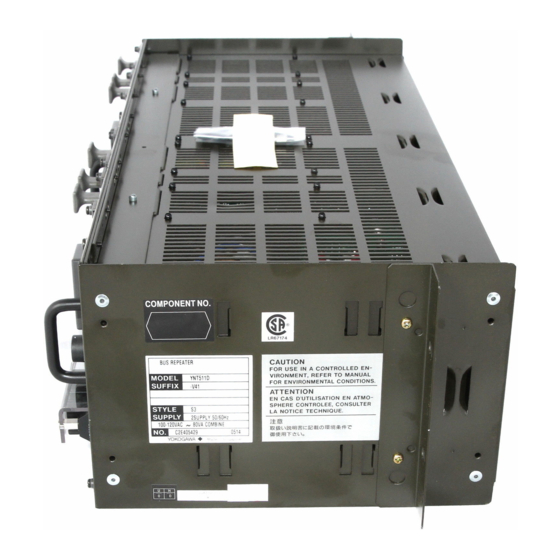
- Page 103 3-25 3. Cabling YNT511S/YNT511D, YNT522S/YNT522D Optical Bus Repeater POWER POWER FUSE 250V 1A FUSE 250V 1A OPTICAL OPTICAL LINK LINK 100-120VAC 100-120VAC Power input terminals Grounding terminal (Connected with M4 screws) F030406.ai Figure Optical Bus Repeater Power Cable Connection YNT512S/YNT512D Bus Repeater Power input terminals Grounding terminal...
- Page 104 3-26 3. Cabling ACG10S Communication Gateway Unit 19-inch Rack Mountable Type Power input terminals Grounding terminal (Connected with M4 screws) Desktop Type Socket F030415.ai Figure ACG10S Power Cable Connection TI 33Q01J10-01E May 18, 2007-00...
- Page 105 3-27 3. Cabling ABC11S/ABC11D Bus Converter READY Power input READY contacts terminals Grounding (Terminal screw: M4) terminal (Connected with M4 screws) F030416.ai Figure ABC11S/ABC11D Cable Connections IMPORTANT If wiring the contact cable to the READY contact output terminals, attach a clamp filter (part No. A1193MN with cable fastener, coming with an ABC11S/ABC11D) supplied with hardware, near the terminals.
- Page 106 3-28 3. Cabling YAX101 General-Purpose Desk TOTAL MAX. Sockets TOTAL MAX. Breaker POWER Rear of desk 100-120 Power input terminals (Terminal screw: M6) Protective earth terminal (Terminal screw: M4) Protective earth mark F030408.ai Figure YAX101 Power Cabling TI 33Q01J10-01E Feb. 1, 2009-00...
- Page 107 3-29 3. Cabling YAX801 General-Purpose Desk Front of desk Rear of desk Power input terminals (Terminal screw: M6) POWER Protective earth mark Protective earth terminal (Terminal screw: M4) Breaker F030413.ai Figure YAX801 Power Cabling TI 33Q01J10-01E Feb. 1, 2009-00...
-
Page 108: Connecting Signal Cable
3-30 3. Cabling Connecting Signal Cable The terminals or connectors of field control station I/O modules interface I/O signals from the field. Process I/O Signal Connection • Power, Control Bus, and signal cables must be separately laid. Avoid laying them in parallel. •... - Page 109 JST Co., Ltd. (Insulators 0.8 mm or more in size are optionally available.) IMPORTANT • For CENTUM CS 3000, spring lugs are used for connecting signals for RIO and for connecting the RIO bus. • Always use solderless lugs with insulated covering.
- Page 110 3-32 3. Cabling Pressure Clamp Terminal (for Pressure Clamp Terminal Block) • Terminal processing When connecting the process I/O signal to the pressure clamp terminal of FIO, strip the cable coating (without a sleeve) or attach a sleeve to the cable. The following shows the length of the coating stripped for cases when a sleeve is not used and when it is used.
- Page 111 3-33 3. Cabling Connecting Signal Cables to Terminals (for FIO) Connecting to Pressure-clamp Terminal Loosen the cable connecting terminal screw. Strip the cable coating (without a sleeve) or attach a sleeve to the cable, then insert the tip of the cable into the connecting section of the pressure clamp terminal. Fasten the screw using the special tool (a screw driver conforming to the DIC 5264B standard with a tip width of 0.6 mm and a shaft diameter of 3.5 mm) with a fastening torque of 0.5 N•m.
- Page 112 3-34 3. Cabling Routing Signal Cables Areas for Signal Cables from Field Signal cables from the field enter the FCS at the bottom and connect to individual node units in the routes shown in Figure below. Front Rear Field wiring area Cable solidification attachment Front : 4points Rear : 4points...
- Page 113 The figure shows a dual-redundant ESB bus example. Front Rear ESB bus ESB Bus ESB Bus MODEL MODEL cable AIP532 AIP532 STYLE1 SI STYLE1 SI YOKOGAWA YOKOGAWA SND-L SND-L SND-R SND-R REVISION REVISION U H1 H2 U H1 H2 To rear of cabinet F030518.ai...
- Page 114 3-36 3. Cabling FIO Node Unit Wiring in I/O Expansion Cabinet The figure shows a dual-redundant ESB bus example, the ESB bus node units installed in the front of the cabinet and the terminal boards in the rear. Avoid using ESB bus cable with other cables and also avoid wiring its cable in parallel with others.
- Page 115 3-37 3. Cabling AFF50S/AFF50D, ANR10S/ANR10D Wiring IMPORTANT To reserve the ventilation for I/O module, the signal cable should not exceed the separator at the center of cable tray. The following shows a dual-redundant ER bus example. ANR10D ER bus cable Power cable Cable tray Power...
- Page 116 3-38 3. Cabling FIO Signal Cabling IMPORTANT The signal cable for the top node unit must be wired at the innermost part in the field control area as the figure shows. When fixing cables to a clamp, allow enough space so that the cards can be maintained. Bind the bottom cables to the clamp bar on the channel base.
- Page 117 3-39 3. Cabling Connecting Signal Cables to Terminals (for RIO) Open the terminal board cover. Loosen the terminal screws. Insert the tip of the cable’s solderless contact between the screw and the spring retainer, and press the retainer to make a gap of about 2 mm between them. Insert the solderless contact further in the gap until the screw enters in the hole of the solderless contact.
- Page 118 3-40 3. Cabling Field Cable Areas Signal cables from the field enter the FCS at the bottom and connect to individual I/O modules in the routes shown in Figure below. Front of Cabinet Rear of Cabinet 19-inch rack mountable type Field cable areas Cable fasteners Front: 9 positions...
- Page 119 3-41 3. Cabling Routing Signal Cables The route of signal cables for field-to-I/O module connections is shown below. RIO Node Wiring in FCU Cabinet The figure shows a dual-redundant RIO bus example. (Front) (Rear) RIO bus cable RIO bus cable RIO bus Distributing unit NIU power...
- Page 120 3-42 3. Cabling RIO Node Wiring in I/O Expansion Cabinet The figure shows a dual-redundant RIO bus example. RIO bus distributing unit RIO bus cables RIO bus cables NIU power supply cables power supply cables Cabinet installation type NIU Signal cables Nodes Signal cable binding...
- Page 121 3-43 3. Cabling Wiring of ANS50/AND50 19-inch Rack Mountable Type Node The following shows a dual-redundant RIO bus example. RIO bus cable NIU power supply cable 19-inch rack mount type node POWER Power cable Signal cable F030513.ai Figure Wiring of 19-inch Rack Mountable Type Node (with I/O expansion rack) TI 33Q01J10-01E Sep.
- Page 122 3-44 3. Cabling Wiring of PFCS/PFCD The following shows a dual-redundant control bus example. V net cable No. 1 No. 2 I/O module I/O module nest nest Power supply cables Power cable No. 3 No. 4 No. 5 I/O module I/O module I/O module nest...
- Page 123 3-45 3. Cabling RIO bus Cabling IMPORTANT The signal cable for the top IOU must be wired at the innermost part in the field control area as the figure shows. When fixing cables to a clamp, allow enough space so that the cards can be maintained. Bind the bottom cables to the clamp bar on the channel base.
- Page 124 3-46 3. Cabling Wiring Console Type HIS When connecting V net cables to a console HIS, lead the cables through the right cable hole. Lead other signal cables through the left cable hole so as to separate them from the V net cables. Wiring of Console Type HIS (LPCKIT) Raise the plate while the system is running...
- Page 125 3-47 3. Cabling Modifying the Cabinet Bottom Plates for Cable Wiring Cables are passed through the holes in the bottom plates of the cabinet. The diameters of these holes can be changed to match the diameter of the cables. There are four bottom plates each at the front and rear of AF20/ACB21 specifically for signal cable wiring.
- Page 126 3-48 3. Cabling To modify the bottom plates, follow these steps. Remove the bottom plate to be modified. Bottom plate Screw Cabinet F030505.ai Figure Removing the Bottom Plate Turn the bottom plate upside down so that the bottom faces upwards. Use a wire cutter or another appropriate tool to remove sections of the bottom plate so that a hole large enough for the cable to pass through is made.
-
Page 127: Connecting Signal Cables With Fieldnetwork I/O (Fio)
Combination of Fieldnetwork I/O (FIO) and Terminal Blocks A pressure clamp terminal block or KS cable (also called a “Yokogawa-specific cable”) interface adapter is available for field-wiring, or an MIL cable provided by the user may be used. For the terminal arrangement of the pressure clamp terminals and terminal board, and the pin arrangement of the ALSO MIL connector, refer to “Field Connection Specifications (for FIO)”... - Page 128 3-50 3. Cabling Terminal block I/O module MIL cable MIL connector Pressure clamp terminal Yokogawa-specific KS cable interface adapter cable F030601.ai Figure FIO Terminals TI 33Q01J10-01E May 18, 2007-00...
-
Page 129: List Of Signal Cables For Connection With Fio
Cannot be connected. Yokogawa-specific cable for connecting I/O Module and a terminal board, etc. Can be connected directly with a Yokogawa-specific cable, without a terminal block. When a MIL connector cable is connected, AAT141 modules can be used as mV-input modules. - Page 130 Digital Output Module (Isolated) – – Can be connected. – : Cannot be connected. Yokogawa-specific cable for connecting I/O Module and a terminal board, etc. Can be connected directly with a Yokogawa-specific cable, without a terminal block. TI 33Q01J10-01E Feb. 1, 2009-00...
-
Page 131: Connecting Signal Cables With Fio
3-53 3. Cabling 3.6.3 Connecting Signal Cables with FIO Pressure Clamp Terminal Signal cable CH16 NC (not connected) Example of Analog module AAI141 F030602.ai Figure I/O Module with Pressure Clamp Terminal Dual-redundant Pressure Clamp Terminal Signal cable CH16 NC (not connected) Example of Analog module AAI141 F030603.ai Figure I/O Module with Dual-redundant Pressure Clamp Terminal... - Page 132 3-54 3. Cabling KS Cable Interface Adapter F030604.ai Figure I/O Module with KS Cable Interface Adapter The I/O modules are arranged in a dual-redundant configuration on the terminal board. Connecting Signal Cables with Analog I/O Module Signal cables are connected to different terminals according to the devices to be connected as listed below: Table Signal Names and I/O Signals of Analog I/O Module...
- Page 133 3-55 3. Cabling Connecting Signal Cables with Pulse Input Module AAP135 The AAP135 receives contact ON/OFF, voltage pulse and current pulse. Refer to the figures below for details on how to connect signal cables since the items to be set by the system generation builder depend on the input pulse types.
- Page 134 3-56 3. Cabling When Receiving Voltage Pulse Signals AAP135 INA 12 V DC/24 V DC Transmitter INB INC Setting Items the system generation builder SW1 (RL) : OFF (No terminating resistor) SW2 (FIL) : OFF (SW1: OFF, SW2: OFF) F030607.ai Figure Voltage Pulse Input When Receiving Current Pulse By Using the Internal Power to Drive the Transmitter (2-wire power supply type)
- Page 135 3-57 3. Cabling Connecting Terminal Board with FIO The I/O module equipped with a KS cable interface adapter can be connected to the terminal board using a Yokogawa-specific cable. Field signals are connected using the terminal board. ANB10D AEA4D F030610.ai Figure Example of Terminal Board Connection with Dual-redundant I/O Module For details of the KS cable interface adapter model and the cable model, refer to “Field Connection Specifications...
- Page 136 Connecting Relay Board with Digital I/O Module An example of the connection of the mechanical relay board ARM55D with the Digital I/O Module ADV551 is shown below. ADV551+ATD5A adapter Yokogawa-specific cable AKB331 Connection with FG ARM55D F030611.ai Figure Example of Relay Board Connection with Digital I/O Module TI 33Q01J10-01E Sep.
-
Page 137: Implementation And Cable Connection Of Fieldbus Communication Module Alf111
3-59 3. Cabling 3.6.4 Implementation and Cable Connection of Fieldbus Communication Module ALF111 This section describes the implementation and cable connection of the Foundation Fieldbus Communication Module ALF111. Foundation fieldbus H1 (Low Speed Voltage Mode) is called Foundation fieldbus, Fieldbus, H1 Fieldbus, FF, or FF-H1 in this manual. - Page 138 Connection of Fieldbus Communication Module ALF111 The Fieldbus can be connected by attaching a pressure clamp terminal block or by using a Yokogawa-specific cable for connection to the terminal board (M4 screw). Connection with a pressure Connection with a terminal board...
- Page 139 3-61 3. Cabling Fieldbus Wiring for ALF111 with Pressure Clamp Terminal Block The signal cables from the field device should be connected to the + and - terminals of the pressure clamp terminal block (ATF9S). Do not connect anything to the terminals of channels that are not used. When installing the node unit mounted with the ALF111 on the 19-inch rack, connect the shield lines of Fieldbus cables from the field devices to the FG terminal of the ATF9S.
- Page 140 3-62 3. Cabling Fieldbus Wiring for ALF111 with Terminal Board ALF111 ALF111 Yokogawa- specific cable AKB336 Use the following fieldbus cables: Cable type Total wire length Type A (*1) 1900 m Type B 1200 m Type D 200 m *1: It is recommended to use Type A cable.
- Page 141 3-63 3. Cabling Installation of Terminator to Terminal Board AEF9D Make sure to install a terminator (YCB138) if the ALF111 (terminal board AEF9D) terminates the network, in other words, if the network is not terminated by a terminator in the power supply unit. Terminal Board AEF9D N.C.
-
Page 142: Connecting Signal Cables With Remote I/O (Rio)
3-64 3. Cabling Connecting Signal Cables with Remote I/O (RIO) This section describes the signal connections with Remote I/O (RIO) used on the AFS10S/ AFS10D, AFG10S/AFG10D, AFS20S/AFS20D, AFG20S/AFG20D, or PFCS/PFCD. 3.7.1 I/O Module Nests I/O Modules Nests are available in the following types: •... -
Page 143: Signal Cables For Connection With Rio
3-65 3. Cabling 3.7.2 Signal Cables for Connection with RIO The following table lists the signal cables for connection with RIO. Table Signal Cables for Connection with RIO I/O Points Per Signal Signal Type Model Module Type Module Connection AAM10 Current/Voltage Input Module (Simplified Type) AAM11 Current/Voltage Input Module... -
Page 144: Connecting Signal Cables With Analog I/O Modules
3-66 3. Cabling 3.7.3 Connecting Signal Cables with Analog I/O Modules Signal cables are connected to different terminals according to type of input and output signal as listed below: Table Analog I/O Module Terminals and Connections Module Terminal I/O signal 2-wire transmitter input + AAM10 2-wire transmitter input -... - Page 145 3-67 3. Cabling Analog I/O Modules AAM10, AAM11, AAM11B, AAM21, AAM21J, APM11, AAM50, AAM51 Analog I/O module AMN11 (slots 1 to 16) Signal cables Temperature compensation module/manual control (for analog output module) channels connector channels Terminals AMN11 Analog I/O module Terminals Temperature compensation/ Recorder output...
- Page 146 3-68 3. Cabling Connecting Signal Cables with Pulse Input Module APM11 The APM11 receives contact ON/OFF, voltage pulse and current pulse. Refer to the figures below for details on how to connect signal cables since the items to be set by the system generation builder depend on the input pulse types.
- Page 147 3-69 3. Cabling When Receiving Voltage Pulse Signals 12 V DC/24 V DC Transmitter OUTPUT Setting Items by the system generation builder SW1 (RL) : OFF (No terminating resistor) SW2 (FIL) : OFF (SW1: OFF, SW2: OFF) F030705.ai Figure Voltage Pulse Input When Receiving Current Pulse By Using the Internal Power to Drive the Transmitter (2-wire power supply type) Transmitter...
- Page 148 3-70 3. Cabling Redundant AAM50/AAM51 These modules output signals of 4 to 20 mA or 0 to 10 V. They may be made redundant when they are set in the current output mode. To make them redundant, two AAM50 or AAM51 modules must be installed in two adjacent slots beginning with an odd-number slot (1-2, 3-4, ..13-14, 15-16) and set to be redundant, and adjacent terminals A and C must be connected to check their outputs against each other as shown below.
-
Page 149: Connecting Signal Cables With Multipoint Control Analog I/O Module Amc80
3-71 3. Cabling 3.7.4 Connecting Signal Cables with Multipoint Control Analog I/O Module AMC80 Multipoint Control Analog I/O Module AMC80 Connect the shield of the Yokogawa-specific cable to the shield terminal. AMN34 Signal Cable (KS1) YOKOGAWA YOKOGAWA Shield AMC80 F030709.ai... - Page 150 When the AMC80 is used in a single configuration, one MCM terminal board is required for each AMC80. IMPORTANT Do not set up AMC80s in the single mode when they are connected to a MCM terminal board in the dual-redundant configuration. AMC80 YOKOGAWA YOKOGAWA KS1 Cable MCM Terminal Board × ×...
-
Page 151: Connecting Signal Cables With Relay I/O Modules
3-73 3. Cabling 3.7.5 Connecting Signal Cables with Relay I/O Modules Relay Input Module ADM15R Output channels C B A Terminal C not used F030711.ai Figure Signal Cable Connection of Relay Input Module ADM15R Relay Output Module ADM55R Output channels C B A A-C: Terminal A (closed when excited) B-C: Terminal B (closed when de-excited) -
Page 152: Connecting Signal Cables With Multiplexer Modules (Terminal Type)
3-74 3. Cabling 3.7.6 Connecting Signal Cables with Multiplexer Modules (Terminal Type) Voltage Input, mV Input, Thermocouple Input, 2-wire Transmitter Input, Current Output Modules AMM12T, AMM22M, AMM22T, AMM22TJ, AMM42T, AMM52T. Only one AMM42T or AMM52T can be installed in one nest. AMN31 Multiplexer Module... -
Page 153: Connecting Signal Cables With Multiplexer Modules (Connector Type)
3. Cabling 3.7.7 Connecting Signal Cables with Multiplexer Modules (Connector Type) Multiplexer Modules (Connector Type) AMM12C, AMM22C, AMM25C, AMM32C, AMM32CJ Connect the shield of the Yokogawa-specific cable to each screw-mount shield terminal. AMN32 Multiplexer Module (Connector Type) Connector Shield Shield... -
Page 154: Connecting Signal Cables With Digital I/O Modules (Terminal Type)
3-76 3. Cabling 3.7.8 Connecting Signal Cables with Digital I/O Modules (Terminal Type) 16-Point Digital I/O Modules ADM11T, ADM51T AMN31 Signal cable Digital I/O Module channel Empty Empty I/O contact Terminals F030716.ai Figure 16-Point Digital I/O Module Signal Cable Connection 32-Point Digital I/O Modules ADM12T, ADM52T Channel common terminals 17 to 32... -
Page 155: Connecting Signal Cables With Digital I/O Modules (Connector Type)
3-77 3. Cabling 3.7.9 Connecting Signal Cables with Digital I/O Modules (Connector Type) Digital I/O Modules ADM11C, ADM12C, ADM51C, ADM52C Connect the shield of the Yokogawa-specific cable to each screw-mount shield terminal. AMN32 Digital I/O Module Connector Shield Shield Screw-mount terminals Connector F030718.ai... -
Page 156: Connecting Signal Cables With Communication Modules
3. Cabling 3.7.10 Connecting Signal Cables with Communication Modules RS-232C Communication Module ACM11 AMN33 YOKOGAWA YOKOGAWA F030719.ai Figure ACM11 Signal Cable Connection Use modem cable KB3 and null modem cable KB4 with a D-sub 25-pin connector. Table RS-232C Interface Connector Pin Positions... - Page 157 3-79 3. Cabling Mounting Clamp Filter (Ferrite Core) (for European Market) When the system is used in Europe, attach a clamp filter (ferrite core) complying with the EMC standard in order to use RS-232C. Mounting Clamp Filter (Ferrite Core) After completing the RS-232C cabling, mount the supplied clamp filter on the covering of the RS- 232C cable to provide enhanced immunity to noise.
- Page 158 3-80 3. Cabling Structure of Clamp Filter and Mounting Unlock the two core lock claws by hand, and the core will open about 150° and split into two pieces as shown in the figure below. Core Lock Claw Cable Connector Core Lock Two Claws RS-232C Cable...
- Page 159 3-81 3. Cabling RS-422/RS-485 Communication Module ACM12 AMN33 RX\+ F030722.ai Figure ACM12 Signal Cable Connection Table RS-422/RS-485 Interface Terminal Positions Terminal Code Signal Name Description Send Data Transmission data (in-phase signals) Send Data Transmission data (phase-reversal signals) Receive Data Receiving data (in-phase signals) Receive Data Receiving data (phase-reversal signals) Signal Ground...
- Page 160 3-82 3. Cabling RS-232C Communication Card ACM21 AMN51 F030723.ai Figure ACM21 Signal Cable Connection Use modem cable KB3 and null modem cable KB4 with a D-Sub 25-pin connector. Table RS-232C Interface Connector Pin Positions Pin Assign Signal Abbreviation Signal Name Description Frame Ground Maintenance grounding...
- Page 161 3-83 3. Cabling RS-422/RS-485 Communication Card ACM22 AMN51 F030724.ai Figure ACM22 Signal Cable Connection Table RS-422/RS-485 Interface Terminal Positions Terminal Code Signal Name Description Send Data Transmission data (in-phase signals) Send Data Transmission data (phase-reversal signals) Receive Data Receiving data (in-phase signals) Receive Data Receiving data (phase-reversal signals) Signal Ground...
- Page 162 3-84 3. Cabling Ethernet Communication Module ACM71 (For PFC) AMN51 F030725.ai Figure Ethernet Communication Module ACM71 Use 10BASE-T, non-shielded, 100-ohm twisted-pair cables for Ethernet connections. Table Pin Assignment of Ethernet Interface Connector (RJ-45) Signal Abbreviation Signal Name Send Data (+) Send Data (-) Receive Data (+) –...
-
Page 163: Connecting The Fieldbus Cable And Handling The Shield Mesh For Fieldbus Communication Module Acf11
3-85 3. Cabling 3.7.11 Connecting the Fieldbus Cable and Handling the Shield Mesh for Fieldbus Communication Module ACF11 AMN33 MAIN 1 MAIN 1 F030726.ai Figure Fieldbus Communication Module Signal Wiring Terminals Connect field signals to the + and - signal terminals (marked 1 and 2 respectively). A clamp filter must be attached to the signal cable as shown. - Page 164 3-86 3. Cabling Use a Type A cable for the connection between the ACF11 and the marshalling rack (shown in dotted box in the figure below), in which the shield of the cable from the field is connected to the ground terminal.
-
Page 165: Connecting Signal Cables With Profibus Communication Module Acp71
3-87 3. Cabling 3.7.12 Connecting Signal Cables with PROFIBUS Communication Module ACP71 F030729.ai Figure PROFIBUS Communication Module ACP71 Use shielded twisted-pair cables for PROFIBUS. Table PROFIBUS Interface Connector Pin Positions Pin position Signal Description Shield N.C. A-Line I/O data CNTR-P Repeater Control Signal D-GND N.C. -
Page 166: Connecting Bus Cable
In this document, 10BASE-5 and 10BASE-2, terminology of Ethernet, are use to describe the V net cables for easier understanding. Actually, V net is different from Ethernet. Yokogawa’s YCB111 and YCB141 cables should be used instead of 10BASE-5 and 10BASE-2 cables. - Page 167 3-89 3. Cabling Connecting V net cables (10BASE-2) Console Type HIS (LPCKIT) Front Rear Bus1 Bus2 PRINTER E X T SLOT1 SLOT2 SLOT3 SLOT4 SLOT5 SLOT6 SLOT7 RS232C-A RS232C-B (COM2) (COM1) Bus1 V net cable (10BASE-2) Bus2 Bus1 VF701 Connector to BNC connector next unit, or (Bus1 side)
- Page 168 Interconnection Example Control Bus Bus1 Bus2 AFS30D Clamp filter ESB Bus ESB Bus MODEL MODEL AIP532 AIP532 STYLE1 SI STYLE1 SI YOKOGAWA YOKOGAWA SND-L SND-L SND-R SND-R REVISION REVISION U H1 H2 U H1 H2 V net (10BASE-5) cable Bus1 Bus2...
- Page 169 3-91 3. Cabling Control Bus Adapter For control buses for the Human Interface Station (HIS) and Compact Field Control Stations for FIO (AFF50S/AFF50D), use V net (10BASE-2) cables. For control buses for field control stations other than the Compact Field Control Stations for FIO, use V net (10BASE-5) cables. The cable conversion adapter is required to connect these two types of cable, which are of different diameters.
- Page 170 3-92 3. Cabling Connecting V net cables (10BASE-5) Bus1 Bus2 AFS30D Clamp filter Control Bus Coupler (Bus2) V net cables (10BASE-5) Bus1 Bus2 To next unit (Attach a terminator if no next unit is connected) PFCD F030804.ai Figure V net Cable (10BASE-5) Connection TI 33Q01J10-01E May 18, 2007-00...
- Page 171 3-93 3. Cabling V net Coupler Installation (ACG10S) The V net couplers of desktop communication gateway can be attached in three ways depending on where bracket is installed, as shown below: • Rack Mounting F030805.ai • Horizontal Side Mounting To connector for Control bus branch connector connecting the V net coupler cable of...
- Page 172 3-94 3. Cabling V net cable (10BASE-5) • V net cable (10BASE-5) • V net terminator (for 10BASE-5 cable) Connection: Type N plug Connection: Type N plug Finished cable dimensions: ø10.3 mm Impedance: 50 ohm F030808.ai Figure V net cable and V net terminator (for 10BASE-5 cable) •...
- Page 173 3-95 3. Cabling • Clamp filter In order to enhance noise resistance, attach three clamp filters in succession at both ends of the V net cable (10BASE-5) near to the V net couplers. Refer to Figure for a typical mounting example. Clamp filter V net Cable (10BASE-5) Clamp filter...
- Page 174 3-96 3. Cabling • BNC Connector Cover If V net (10BASE-2) cables are connected to the AFF50, install BNC connector covers to prevent the BNC connectors from coming into contact with other pieces of metal. Four BNC connector covers are supplied with the AFF50. V net branch connector Cover...
- Page 175 ESB bus branching connector. If the node unit is the last one, select the branching connector that has a built-in ESB bus terminator. AFS30D ESB Bus ESB Bus MODEL MODEL AIP532 AIP532 STYLE1 SI STYLE1 SI YOKOGAWA YOKOGAWA SND-L SND-L SND-R SND-R REVISION REVISION U H1 H2 U H1 H2 Screw tightening torque...
- Page 176 3-98 3. Cabling AFF50D Screw tightening torque 0.291±0.049 N•m FUSE RL1 100-120V AC , CN1 (PSU-L) READY (CPU-L) (CPU-R) (CPU-L) (CPU-R) ENBL ENBL CN2 (PSU-R) DSBL DSBL ESB coupler ESB bus cable (YCB301) (EC401) Bus1 Bus2 SB401+ SB401+ S9879UK S9879UK ESB bus (duplexed) (connected to Bus1 if single) to next node unit...
- Page 177 3-99 3. Cabling ER Bus The following is an example of connecting an ER bus. If no next station is connected, attach YCB148 Terminator. Avoid using ER bus cable with other cables and also avoid wiring its cable in parallel with others. ESB bus node unit ANB10D EB401...
- Page 178 3-100 3. Cabling How to wiring ER bus The figure shown below describes how to wiring ER bus: EB401 Terminator (YCB148) Clamp filter (A1193MN) ANB10D Fix with using a cable fastener at the front right edge of cable tray. YCB141 Separate from other cables.
- Page 179 3-101 3. Cabling Terminator Regarding EB401 and EB501, if one side of T-type connector is terminal, mount a terminator. Two terminators are supplied with EB401. Clamp Filter Regarding EB401 and EB501, mount clamp filters to both side of T-type connector. If one of the sides is terminal, mount a clamp filter to only the cable side.
- Page 180 3-102 3. Cabling ER Bus Converting Adapter The converting adapter is required when connecting 10BASE-2 and 10BASE-5 cable. For more information about the converting adapter, see the following: ALSO “● Control Bus Adapter” in “3.8 Connecting Bus Cable” 10BASE-5 Cable When 10BASE-5 cable is used, a grounding unit (YCB117) should be used for grounding.
- Page 181 3-103 3. Cabling RIO Bus The following is an example of connecting an RIO bus. If no next station is connected, attach YCB128 Terminator. RIO Bus (19-inch Rack Mountable Type) AFS10D To next node (or terminated if the FCU is the last node) Bus 1 Bus 2 RIO bus coupler connection terminals...
- Page 182 3-104 3. Cabling RIO Bus (with Cabinet) Front of cabinet Rear of cabinet RIO bus unit From other node RIO bus coupler connection terminals Bus 1 Bus 2 To next node (or terminated if the FCU is the last node) Bus 1 Bus 2 NIU connection...
- Page 183 3-105 3. Cabling RIO Bus Arrangement [1] or [4] (Tin-plated semitransparent covering or blue) [2] or [5] (Copper wire with semitransparent covering or white) [3] or [6] (Gray covering or green) Shield Finished cable dimensions: ø8.5 mm Connection: M4 Screw F030816.ai Figure RIO bus Cable •...
-
Page 184: Connecting Optical Fiber Cable
3-106 3. Cabling Connecting Optical Fiber Cable The optical bus repeater is used to convert part of the system’s communication bus to optical fiber cables. The optical fiber cables must be provided by user. Connect the optical transceivers of a pair of optical bus repeaters as shown below: Optical connector OPTICAL OPTICAL... - Page 185 3-107 3. Cabling To Use GI 62.5/125 Optical Fiber Cable It is recommended to use a GI 50/125 optical fiber cable (core diameter 50 µm, clad diameter 125 µm) for an optical bus repeater. To use a GI 62.5/125 optical fiber cable, follow the procedure below. Compared to a GI 50/125 optical fiber cable, a large volume of light is emitted by connecting a GI 62.5/125 optical fiber cable to the output connector of an optical bus repeater.
-
Page 186: Alarm And Contact I/O Cabling
3-108 3. Cabling 3.10 Alarm and Contact I/O Cabling CAUTION It is recommended to use signal cables, relay terminals, relays, power units, and other devices that comply with CSA 61010-1 or CSA 60950-1 (for 100-120 V AC) or EN 61010-1 (for 220-240 V AC) standards when connected to contact output terminal. - Page 187 3-109 3. Cabling Use of Relays Contact protection and surge absorption can be provided in various manners. When using contacts output to drive relays and solenoids, the following precautions should be taken: • Install a diode in parallel to induction load for noise prevention and contact protection. •...
-
Page 188: Installation Specifications
4. Installation Specifications Installation Specifications This section summarizes power consumption, in-rush current, breaker ratings, parts durability and other data for the installation of CS 3000 system. Electrical Specifications Power consumption (current) and other electrical data are shown below: Table Electrical Specifications (1/3) Max. - Page 189 4. Installation Specifications Table Electrical Specifications (2/3) Max. power Heating Input-voltage range Equipment consumption value J/h Voltage (V AC) Frequency (Hz) (VA, A) (*1) (*2) 100-120 200 VA 50/60±3 680 × 10 PFCS field control station (excl. I/O) 220-240 300 VA (190 W) 24 V DC 100-120...
- Page 190 4. Installation Specifications Table Electrical Specifications (3/3) Max. power Heating Input-voltage range Equipment consumption value J/h Voltage (V AC) Frequency (Hz) (VA, A) (*1) (*2) 100-120 200 VA 50/60±3 ANB10D Duplexed ESB Bus Node Unit 432 x 10 220-240 230 VA (at maximum installation of FIO) (120 W) 24 V DC...
- Page 191 4. Installation Specifications Actual Power-On In-Rush Current of Each Component Actual in-rush current data measured for each component is listed below: Table System Equipment Power-On In-Rush Current In-Rush current (A) In-Rush current (A) In-Rush current (A) Model 100 V AC 220 V AC 24 V DC Primary Secondary Primary Secondary Primary Secondary...
- Page 192 4. Installation Specifications Input current peak values and waveforms, influenced by input impedance, varies with system configurations, line sharing with other systems, and other factors. The rush current data shown above were measured under predetermined conditions (see below). Please note that the values are subject to change.
- Page 193 4. Installation Specifications Maximum Power Consumption of FIO Table Maximum Power Consumption of FIO (1/2) Max. current Max. current Model Name consumption consumption name 5 V DC (mA) 24 V DC (mA) Bus Interface Module EB401 ER Bus Interface Master Module –...
- Page 194 4. Installation Specifications Table Maximum Power Consumption of FIO (2/2) Max. Current Max. current Model Name consumption consumption name 5 V DC (mA) 24 V DC (mA) Digital I/O Modules ADV151 Digital Input Module (32-channel, 24 V DC) – ADV551 Digital Output Module (32-channel, 24 V DC) –...
- Page 195 4. Installation Specifications Maximum Power Consumption of RIO Table Max. Power Consumption of RIO (1/2) Max. Power Module Name Consumption 5 V DC (A) Analog I/O modules AAM10 Current/voltage input module (simplified) 0.25 AAM11 Current/voltage input module AAM11B Current/voltage input module (for BRAIN type) AAM21 mV, thermocouple, resistance temperature detector input module 0.15...
- Page 196 4. Installation Specifications Table Max. Power Consumption of RIO (2/2) Max. Power Module Name Consumption 5 V DC (A) Digital I/O modules ADM11T Contact input module (16-contact, Terminal type) ADM12T Contact input module (32-contact, Terminal type) ADM51T Contact output module (16-contact, Terminal type) ADM52T Contact output module (32-contact, Terminal type) ADM11C...
- Page 197 4-10 4. Installation Specifications Breaker Specifications Breaker ratings are listed below: Table Breaker Ratings (1/2) Built-in breaker rating External breaker rating Equipment (A/V) (Recommend) (A/V) (*1) LPCKIT, YPCKIT console assembly (100 V AC) 15/250 30/250 LPCKIT, YPCKIT console assembly (220 V AC) 15/250 30/250 PFCS field control station (100 V AC system)
- Page 198 4-11 4. Installation Specifications Table Breaker Ratings (2/2) Built-in breaker rating External breaker rating Equipment (A/V) (Recommend) (A/V) (*1) AFS30S/AFS30D, AFG30S/AFG30D field control unit (100 V AC) 8/250 (fuse) 15/250 AFS30S/AFS30D, AFG30S/AFG30D field control unit (220 V AC) 8/250 (fuse) 15/250 AFS30S/AFS30D, AFG30S/AFG30D field control unit (24 V DC) 15/25 (fuse)
- Page 199 The average ambient temperature shown in the table is the average temperature surrounding the corresponding parts. When the parts are installed in a cabinet of Yokogawa product, though varies with actual installations, in general, the temperature inside of the cabinet is about 10 °C higher than the temperature outside the cabinet.
- Page 200 Fuse S9518VK 3 years for fan 100000 Relay S9725VM – operations Users can replace a fan unit by themselves, but they are also required to do soldering. YOKOGAWA service department can take on the work. TI 33Q01J10-01E Feb. 1, 2009-00...
- Page 201 4-14 4. Installation Specifications LOPXLMK Table Periodic Replacement Parts Having Defined Life Spans (When average LOPXLMK ambient temperature is 30 °C) Recommended Part Replacement Part names replacement Remarks numbers by user cycle Air filter T9050NY 1 year Wash every 3 months. The electrolytic capacitor is a Power supply unit S9961UK...
- Page 202 4-15 4. Installation Specifications AFS10, AFG10/AFS20, AFG20/ACB21, ACB41/ ANS50/AND50, ANS20/ AND20 Table Periodic Replacement Parts Having Defined Life Spans Used in: Recommended Part Part Replacement replacement Remarks names numbers by user cycle 100 V AC (PW301) 8 years Average ambient temperature 40 °C or less...
- Page 203 4-16 4. Installation Specifications AFS30, AFG30/AFS40, AFG40/ANB10/ANR10 Table Periodic Replacement Parts Having Defined Life Spans Used in: Recommended Part Part Replacement replacement Remarks names numbers by user cycle 100 V AC (PW301) 8 years Average ambient temperature 40 °C or less 220 V AC (PW302) 8 years...
- Page 204 4-17 4. Installation Specifications AFF50 Table Periodic Replacement Parts Having Defined Life Spans Recommended Part Replacement Part names replacement Remarks numbers by user cycle 100 - 120 V AC PW481 8 years Average ambient temperature 40 °C or less 220 - 240 V AC Power supply PW482 8 years...
- Page 205 4-18 4. Installation Specifications YNT511/YNT522 Optical Bus Repeater and YNT512 Bus Repeater Table Periodic Replacement Parts Having Defined Life Spans Recommended Part Replacement Part names replacement Remarks numbers by user cycle Power unit PW501 8 years Average ambient temperature 40 °C or less (100-120 V AC) Power unit PW502...
- Page 206 4-19 4. Installation Specifications ABC11S, ABC11D Table Periodic Replacement Parts Having Defined Life Spans Part Recommended Replacement Part names Remarks numbers Replacement Interval by user 1 year Clean it every three months Air Filter T9070CK 4 years AIP601 3 years Average ambient temperature 30 °C or less 1.5 years Average ambient temperature 40 °C or less...
- Page 207 4-20 4. Installation Specifications Notes for Installing Devices This section describes notes for installing devices and installation restrictions. Rules of Connection for the Housekeeping Unit (HKU) The HKU owns a function which controls temperature rises by rotating the fans at high speed if the intake temperature becomes 35 °C or more, or the exhaust temperature becomes 40 °C or more in the I/O expansion cabinet (ACB21).
-
Page 208: Post-Installation Inspection And Environmental Preservation
No dust remaining inside cabinet It is recommended that you turn on the power in the presence of Yokogawa when turning it on first. Post-installation Environment Preservation... - Page 209 Ind-1 CENTUM CS 3000 Installation Guidance TI 33Q01J10-01E 13th Edition INDEX Symbols Ambient Temperature .........1-32 Analog I/O Modules AAM10, AAM11, AAM11B, 16-Point Digital I/O Modules ADM11T, ADM51T AAM21, AAM21J, APM11, AAM50, AAM51 ..............3-76 ..............3-67 19-inch Rack-mount Devices and Wiring ...3-24 Analog Input Modules AAM21, AAM21J for 19-inch Rack Mount Devices ......2-23...
- Page 210 Ind-2 Concrete Floor ............ 2-11 Connecting V net cables (10BASE-5) and V net cables (10BASE-2) Interconnection Condensation ............1-5 Example ............3-90 Conduit Power-cabling ........3-10 Connection of Fieldbus Communication Module Connecting Bus Cable ........3-88 ALF111 ............3-60 Connecting Ground Cable ........3-11 Connector Type IOU Cabling ......3-45 Connecting Optical Fiber Cable ......3-105 Connector Type Multiplexer Module and Terminal...
- Page 211 Ind-3 FIO with KS Cable Interface Adapter Cabling ..3-38 Flooding- & Dust-proof Floor ........ 1-2 List of Signal Cables for Connection Floor Strength and Space ........1-2 with FIO ............3-51 Floor Structure ............1-2 Loading ..............2-2 “Free-access” Floor ..........2-12 Location for Unloading ..........
- Page 212 Ind-4 Paint Colors ............4-19 Safety Standards ..........1-8 Parts Durability ............4-12 Selecting a Power System ........1-16 Passage ..............2-4 Separate Grounding ...........1-22 PFCS/PFCD Field Control Station .....3-18, 4-17 Separator ............1-31 Post-installation Environment Preservation ..5-1 Servicing Area ............2-9 Post-installation Inspection ........5-1 Side-by-Side Cabinet Installation ......
- Page 213 Ind-5 Unloading .............. 2-3 YAX101 General-Purpose Desk ......3-28 Unpacking ............. 2-6 YAX801 General-Purpose Desk ......3-29 Unpacking Procedure ........... 2-7 YNT511/YNT522 Optical Bus Repeater and YNT512 Bus Repeater ........4-18 Use of Lamps ............3-107 YNT511S/YNT511D, YNT522S/YNT522D Optical Use of Relays ............3-108 Bus Repeater ..........3-25 Using Rollers ............
- Page 214 Blank Page...
- Page 215 Revision Information Title : CENTUM CS 3000 Installation Guidance Manual No. : TI 33Q01J10-01E May 1998/1st Edition Newly published Nov.1998/2nd Edition 1. System Environment Installation Environment Spec. Vibration conditions (Acceleration formula changed) Installation environment (Magnetic field, vibration during...
- Page 216 3. Cabling 3.1 Cables & Terminals Revised descriptions of "Power Cables" and "Grounding Cables" Revised figure showing Solderless Terminal with Insulating Sheath in "Cable Terminals" 3.2 Connecting Power Revised table of Solderless Lug Dimensions in "Power Cable Termination" 3.4 Power and Ground Cabling LIH21C changed to LPH21C Added "Power Wiring When Connecting Dual Power Supply Lines"...
- Page 217 2. Transportation, Storage and Installation 2.1 Precautions for Transportation Revised title of "Lifting Console Type HIS with Crane" to "Lifting Enclosed Display Style Console Type Kit (LPCKIT) with Crane 2.4.1 Installation on Floor Added description of YPCKIT 2.4.2 Console Type HIS (LPCKIT) Side-by-Side Revised table of Tools and Parts Required for Joining a Pair of HIS 2.4.4 19-inch Rack Mount Devices Added AFS30S/AFS30D and ANR10S/ANR10D...
- Page 218 1.8 Corrosive-gas Environment Compatibility Revised Table 2. Transportation, Storage and Installation 2.1 Precautions for Transportation Added "Transportation for LPCKIT,YPCKIT" in "Transportation" Title changed "Lifting Console Type Kit (LPCKIT,YPCKIT) with Crane" 2.4.1 Installation on Floor (Added description) 2.4.2 Console Type HIS Side-by-Side (changed title) Added "YPCKIT"...
- Page 219 Dec. 2002/6th Edition Main revision items of this revision Described about LCD unit used in the enclosed display style console type HIS Updated the description of the applied standards Added 16-channel isolated I/O modules Added I/O modules with the built-in barrier Described more information about the signal cable connection with I/O modules and their installation restrictions Vibration: Revised the expression of “total amplitude”...
- Page 220 Added AFF50S/AFF50D Field Control Units to Terminal Connection Added AFF50S/AFF50D figures Added FG to ANB10S/ANB10D figures Added FG to ANR10S/ANR10D figures Added figures with ANR10S/ANR10D installed in general-purpose cabinet Corrected coating stripped length data for Pressure Clamp Terminal with a sleeve Deleted FG from ANR10S/ANR10D figures 3.6.2 Added AAV144, AAV544, and ALP111 module signal cable connections to Table Signal Cables for Connection with FIO...
- Page 221 Oct.2004/8th Edition 1. System Installation Requirement 1.2 Control Room Environment Table of Equipment Installation Specification modified All of Non-Incendive Approval and parameter deleted. For Non-Incendive, refer to TI33Q01J30-01E Explosion Protection. 1.8 Corrosive-gas Environment Compatibility G3 Environment-compatible Products AFF50 and AAP849 added to G3 Environment-compatible Products. 3.
- Page 222 viii May 2007/10th Edition 1. System Installation Requirements 1.1 Control Room Design Clearance From The Wall and The Floor Surface A desk (YAX101,YAX801) add. 1.2 Control Room Environment Temperatures and Humidity Description is modified. Applied Standard Standards for Hazardous Location Equipment EN 50021:1999 of [Type n] is replaced with EN 60079-15:2003, IEC 60079-0:1998 and IEC 60079-11:1999.
- Page 223 4. Installation Specifications Electrical Specifications YNT521 is replaced with YNT522. Actual Power-On In-Rush Current of Each Component YNT521 is replaced with YNT522. The content of “ACG10S Communication gateway unit” is modified. Maximum Power Consumption of FIO Description of “AAV542” , “AAI135” , “AAI835” and “AAP135” is modified. Breaker Specifications YNT521 is replaced with YNT522.
- Page 224 Sep.2008/12th Edition Safety Precautions Wiring I/O Cables [Changed the number CSA 1010 to CSA 61010] 1.1 Control Room Design Side-by-Side Cabinet Installation [Revised the description] 1.2 Control Room Environment Electric field strength (Electric ware condition) [Title changed and revised the description] Safety Standards [Changed the CSA C22.2 number 1010.1 to 610101-04] EMC Conformity Standards [Changed the AS/NZS number 2064 to CISPR 11] Standards for Hazardous Location Equipment [Revised the description] [Changed EN and IEC...
- Page 225 Blank Page...
- Page 226 Written by Yokogawa Electric Corporation Published by Yokogawa Electric Corporation 2-9-32 Nakacho, Musashino-shi, Tokyo 180-8750, JAPAN Printed by KOHOKU PUBLISHING & PRINTING INC. Subject to change without notice.
Need help?
Do you have a question about the CENTUM CS 3000 and is the answer not in the manual?
Questions and answers