
Related Manuals for YOKOGAWA Field Mate 3


Summary of Contents for YOKOGAWA Field Mate 3
- Page 1 Volumetric Displacement Fertilizer ontrol System Users Guide Installation Manual...
- Page 2 Ver 1.0 FIELD MATE USER MANUAL If you Need to Call Customer Service Please complete the following information for future reference: Field Mate Model* :............Serial Number * :..............Date Purchased :..............Place of Purchase:............... * The Serial/Model Number is displayed in the Information Screens of the meter.
-
Page 3: Warranty
Warranty : 1 Year return to factory Warranty on Electric Drive components, sensors and Downloading support hardware. Please ensure you agree to the warrantry conditions before proceeding to purchase this product, read the warranty form at the end of this user guide. Installation wiring to sensors and wear and tear on connectors not covered NOTE: Gtech Zealand... -
Page 4: Specifications
SPECIFICATIONS Specifications: Supply volts 5 – 15 Volts Monitor Current 75ma Temperature -5 to 55 degree/C Input voltages 0 to 30 Volts Max Width 99.99 Meters Distance 999.99 km Max Speed 20 km/Hr Wheel Size 999.9 cm Max Motor Amps : 20 amps per motor Features: - Up to 4 metering unit motors... - Page 5 Wiring Connections: 12 Pin Connector 1- Ground Speed Black Ground signal to all sensors Speed Yellow Speed pulse (Switch to GND to trigger) 5- Hold White Hold signal (Switch to GND to trigger) Distance Green GPS Sync Pulse (Switch to GND to trigger) Brown Blue Brown Green...
-
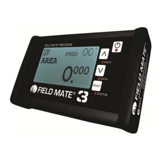
Page 6: Main Screen
system voltage ain Screen Ground speed State machine status. Relects fert release function control Current distance travelled from sync pulse Sync pulse spacing Last distance travelled from sync pulse plant counter The fert distance counts down here. paint pump status paint solenoid time in milli seconds... - Page 7 Job Screen details (Enter the JOB screens by Quick pressing the POWER key) Inside the JOB menu... Change the job Hold ARROW key to select Bin1 libary select . Currently set to 1 Bin2 libary select . Currently set to 1 Current JOB.
- Page 8 Option Screen details (Enter the OPERATE screens by Quick pressing the POWER key) Quick Press the POWER key to enter the OPERATE mode. Inside the OPERATE menu... (Move through the OPERATE screens using the ARROW keys - Quick Press!) Area Drill for the current job SUB AREA drilled for this job.
- Page 9 Inside the OPERATE menu. More.. Working RATE of the Drill. Displayed in Hectare/Hour.
- Page 10 Setup Screen details (Enter the SETUP screens by Quick pressing the POWER key) Quick Press the POWER key to enter the SETUP mode. NOTE: When exiting SETUP turn the monitor OFF then ON. If not done "CYCLE POWER" will flash and the motors will not run.
- Page 11 REPORT Screen details (Enter the REPORT screens by Quick pressing the POWER key) Quick Press the POWER key to enter the REPORT mode. Inside the REPORT menu... (Move through the REPORT screens using the ARROW keys - Quick Press!) - Name of BIN1 - Name of BIN2 - Name of BIN3 - Name of BIN4...
- Page 12 Inside the REPORT menu. More.. - Time with the drill in RUN mode and Drilling. - Time with the drill in RUN mode and stationary. - Time with the drill in HOLD Mode, with the drill moving. - Time with the drill in HOLD Mode, the drill is stopped.
- Page 13 Inside the REPORT menu. More.. - Total time spent drilling. This time includes all times, moving and stopped. - Number of Speed pulses counted while drilling. - Number of speed pulses counted while not drilling, in HOLD mode. - Size of the DISTANCE PULSE number used to calc the area for this job.
-
Page 14: Info Screen
INFO Screen (Enter the INFO screen by quick pressing the POWER key) Quick Press the POWER key to enter the INFO screen. Inside the INFO menu... (Move through the INFO screens using the ARROW keys - Quick Press!) LOGO HELP DESKphone number. - Page 15 Inside INFO menu... more Monitor Model Firmware version - Time monitor been powered - Time moniotr been drilling - Life time hectare drilled - Backlight volatge status ware error detection system. These counter will increment every time software vectors these error detection system...
- Page 16 Inside menu... more - Real Time Clock status - Run Hold Status Area calculation support Time support - Buzzer status Back ground numbers AREA calculation Total Area support numbers - Rate Reduction feature status...
Need help?
Do you have a question about the Field Mate 3 and is the answer not in the manual?
Questions and answers