
Related Manuals for TeeJet SENTRY 6510


Summary of Contents for TeeJet SENTRY 6510
- Page 1 S E N T R Y 651 0 CAPACITY MONITOR O P E R AT O R S M A N U A L & F I T T I N G I N S T R U C T I O N S Firmware version 1.10...
- Page 2 Copyrights © 2014 TeeJet Technologies. All rights reserved. No part of this document or the computer programmes described in it may be reproduced, copied, photocopied, translated, or reduced in any form or by any means, electronic or machine readable, recording or otherwise, without prior written consent from TeeJet Technologies.
-
Page 3: Table Of Contents
Sentry 6510 Capacity Monitor Table of contents INSTALLATION General overview ........................................2 Electrical connections ......................................4 Fitting the monitor ....................................... 5 Fitting the junction box ...................................... 5 Connecting the power supply ..................................5 Mounting the wheel sensor ....................................6 Fitting the walker pads ....................................... 7 Connecting the walker pad cables ..............................7... -
Page 4: Installation
Sentry 6510 Capacity Monitor INSTALLATION General overview Figure 1: System diagram 06, 07 www.teejet.com... - Page 5 Sentry 6510 Capacity Monitor Item Part number Description 902-630 TeeJet Sentry 6510 Capacity Monitor 198-716 Main cable 907-012 Straw walker sensor 841-521 Sieve sensor bracket 198-312 Sieve sensor cable 866-012 Junction box 900-013 Circuit board 901-982 Speed sensor 775-803 Magnet...
-
Page 6: Electrical Connections
Sentry 6510 Capacity Monitor Electrical connections Figure 2: Close-up of electrical wiring +12V www.teejet.com... -
Page 7: Fitting The Monitor
3. Attach the monitor to the bracket as shown in Figure 3. NOTE: The Sentry 6510 Capacity Monitor uses the same connection as the LH500C Combine Computer. If the combine harvester already has an LH500C installed, simply connect the cable from the monitor to the port on the main cable. -
Page 8: Mounting The Wheel Sensor
Sentry 6510 Capacity Monitor Mounting the wheel sensor Mount the wheel sensor to the frame on the inside one of the steering wheels. Mount the magnet to the wheel hub or rim using the 20 mm support collar. 1. Screw or weld the sensor bracket. -
Page 9: Fitting The Walker Pads
Sentry 6510 Capacity Monitor Fitting the walker pads Mount the two walker pads at the rear of the two outside straw walkers. NOTE: Account for any reinforcements and walker extensions when positioning the walker pads. 1. Stick the supplied adhesive templates on the underside of the walkers with the arrow pointing to the rear of the walkers. -
Page 10: Fitting The Sieve Sensor
Sentry 6510 Capacity Monitor 2. Turn the straw walker to its lowest position and mark the side of the combine harvester (position A in Figure 9) at a right angle to the cable fastener. Figure 8: Straw walker mark angle 3. -
Page 11: Shortening The Sensor
Sentry 6510 Capacity Monitor On some combine harvesters, it may not be possible to fit the sensor in the recommended position due to placement of other parts, such as an adjustment handle. In these cases, the sensor can be mounted higher or lower than 50 mm under the sieves. In any case, the centre of the sensor must not be higher than the edge of the sieve, or lower than 100 mm under the sieve. -
Page 12: Connecting The Sieve Sensor Cables
Sentry 6510 Capacity Monitor Figure 14: Bung and spacer placement 5 mm 7. Tighten the nuts so that the rubber swells slightly. NOTE: The bolts in the bung must not touch the plastic spacer. Connecting the sieve sensor cables 1. Connect the plug to the sensor. -
Page 13: Operation
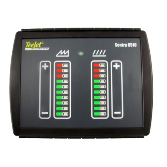
Sentry 6510 Capacity Monitor OPERATION User interface Figure 17: User interface buttons Press to increase reading Press both to set reading to 50% Press to decrease reading Straw walker Sieve loss loss bar graph bar graph The LEDs on each bar graph indicate the current relative loss value as measured by the straw walker sensor and the sieve sensor. -
Page 14: Calculation Of Grain Loss
Sentry 6510 Capacity Monitor Calculation of grain loss This table indicates the number of lost seeds per metre of straw behind the combine harvester when the loss is 1% and the field yields 4000 kg/ha. Width of cut Barley Oats... -
Page 15: Setting Up The Capacity Monitor
Sentry 6510 Capacity Monitor Setting up the capacity monitor Not even the best capacity indicator can prevent grain from being lost. The purpose of the monitor is to inform the operator of the approximate amount of grain being lost. It is also important to understand that the loss readings from the monitor are not absolute measurements, but are instead meant to indicate how the loss is perceived when harvesting variables change. -
Page 16: Display Indications
Sentry 6510 Capacity Monitor Display indications A correctly adjusted monitor will indicate with the LEDs both the relative grain loss and when the combine harvester capacity is being fully utilized. Figure 20 describes the conditions that different readings indicate. Figure 20: LED loss and capacity indications •... -
Page 17: Storage Of Values
Sentry 6510 Capacity Monitor Storage of values When + or - is pressed, the gain for both graphs are saved to the monitor. When the monitor is turned off, these gain values are preserved. When the monitor is restarted, it begins working at the gain settings applied before power off. - Page 18 SENTRY 6510 CAPACITY MONITOR OPERATORS MANUAL & FITTING INSTRUCTIONS www.teejet.com 990-630-EN-A4 R0 English © TeeJet Technologies 2014...
Need help?
Do you have a question about the SENTRY 6510 and is the answer not in the manual?
Questions and answers