Advertisement
Quick Links
The Savant SmartMedia (SSM-3000) Surround Sound Quick Reference Guide provides all
the steps necessary to install the SmartMedia Controller.
Box Contents
(1) SmartMedia (SSM-3000)
(1) Installation Kit (075-0075-xx)
(4) Screw m5 x 12mm (039-0034-xx)
•
(1) Power cord C13, 6 feet (N. America) (064-0079-xx) or appropriate international
•
power cord
(2) 6-Pin Screw-down Plug in Connector (028-9352-xx)
•
(2) 3-Pin Screw Down Plug in Connector (028-9351-xx)
•
(2) Rack Mounting Brackets (2U) (071-0113-xx)
•
(1) 1HDMI Locking Cable, 3 feet (CBL-3LHDMI-xx)
•
(1) Quick Reference Guide (this document)
Specifications
Environmental
Temperature
32º to 104º F (0º to 40º C)
Humidity
10% to 80% Non-condensing
Cooling
10 cubic feet per minute (CFM) recommended.
Maximum BTUs
188 BTUs per hour
Dimensions and Weight
Dimensions (H x W x D)
3.46 in x 17.30 in x 12.94 in (8.79 cm x 43.94 cm x 32.88 cm)
Weight
15.5 lb/7.03 kg
Power
Supply
100-240V AC, 50/60 Hz
Nominal Power Draw
35 Watts
Maximum Power Draw
55 Watts
Compliance
Safety and Emissions
S Mark/FCC Part 15 /CE Mark /C-Tick
RoHS
Compliant
1
On/Off button
Insert pin into hole for about 10 seconds to place in standby
(hole)
mode. Insert the pin again for about 1 second to take system out
of standby mode. The 1/0 power switch on the back of Controller
must be On (1) to enable this function. To turn the power off for
the entire system, use the switch on the rear panel.
2
Power Bi-color LED
Green indicates the system has adequate power and is operating
normally.
Red indicates the system is in stand-by mode. In standby most of
the Controller circuitry is powered down.
Off indicates that the system is getting no power.
3
Status Bi-color LED
Green indicates the Host has established communications with
the embedded system.
Green flashing indicates the embedded system is ready (running
with DHCP IP address), but the Host has not established
communications with the embedded system.
Off indicates the embedded processor is resetting or is powered
up; and is booting the embedded firmware.
Red indicates the Host has determined the firmware needs to be
updated, but a problem occurred during the process that will
initiate a reset.
Red flashing indicates the embedded firmware is running, but
has not received a DHCP IP Address.
Amber indicates the Host is currently updating the embedded
firmware.
Amber flashing indicates the embedded system has a valid link-
local IP Address and is waiting to connect to the Host.
Over Temperature or Hardware Failure
If the Controller over heats or has a hardware failure, the Status
LED indication will be interrupted every 3-seconds with a solid
red indication. For example, if the LED is flashing green when an
over temperature or hardware failure occurs, the LED, in 3-
second intervals, will flash green, solid red, etc.
4
RS-232 LED
Green indicates RS-232 serial port data activity.
Off indicates no RS-232 serial port activity.
5
GPIO LED
Green indicates GPIO port signal activity.
Off indicates no GPIO port activity.
6
OSD Present LED
Green indicates the external host is connected to the Host HDMI
port
Off indicates the external host is not connected to the Host HDMI
port.
7
Video LED
Off indicates the encrypted video content remains protected. The
HDCP keys remain valid.
Red flashing indicates the HDCP keys are invalid.
8
IR LED
Green indicates IR port signal activity.
Off indicates no IR port activity.
9
Relay LED
Green indicates Relay port signal activity.
Off indicates no Relay port activity.
Copyright © 2012 Savant Systems LLC, SAVANT and RacePoint Blueprint are trademarks of Savant Systems, LLC.
All brand names, product names and trademarks are the property of their respective owners.
Savant Systems, LLC reserves the right to change product specifications without notice.
Quick Reference Guide
45 Perseverance Way, Hyannis, MA 02601
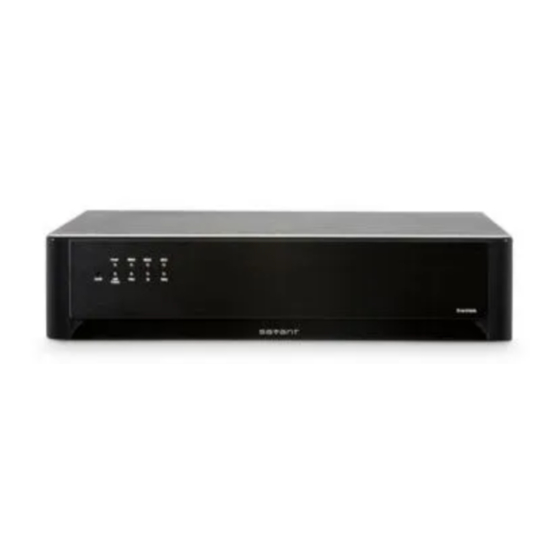
Savant SmartMedia
(SSM-3000)
1
8 9
10
1
Digital Audio In: 1, 2
2
Stereo In: 1,2,3,4
3
GPIO
GPIO Outputs
4
Audio Out 7.1
5
Stereo Out
6
1/0
7
Fuse
8
Reset button
9
Ethernet
10
RS-232
11
Relay NC/C/NO
(Normally
Closed/Common
Normally Open)
12
IR 1 - 6
13
Host HDMI
14
HDMI Out
15
VGA
16
Digital Audio Out
17
Video Component In
18
HDMI In
19
Input Power
Wiring and Connectors
RS-232 Wiring
Controller RJ-45 (RS-232) Plug Pinouts
1
(Not Used for RS-232)
2
(Not Used for RS-232)
3
(Not Used for RS-232)
4 GND (RS-232)
Important
If you are using RJ-45 to DB-9 adapters not supplied by Savant, be sure to terminate any
wires required for communication/control within the adapter. Ensure that all wires required for
communication/control are not terminated in the connecter. Also, ensure that the unused
wires in the connector are cut to prevent them shorting out, as they are still terminated in the
RJ-45 connector on the controller side
For more details on RS-232, RS-422 and RS-485 connectors, go to
>Dealer Login > Knowledge Base > Products
Refer to the RS-232/RS Conversion to DB-9 and RS-422/485 Pinout Application Note
•
Phone 508.683.2500
Fax 508.683.2600
2
3
4
5
16 17
11
12 13
14
15
Input ports support TosLink to receive digital audio signals
Right and Left (8) RCA jacks for audio input
General Purpose Input and Output ports—uses 3-pin screw-
down connector
The digital GPIO ports are binary I/O ports used for contact
closure, trigger (output), or detect (input). R is reserved (not
used). The COM pin is used for common ground. Pin 1 is
used for input or output.
GPIO Inputs
When configured as an input, the port detects a voltage
present (GPIO input). GPIO inputs can safely detect the
presence of a voltage of 0-30V DC with a high/low threshold
of approximately 2.4V DC.
When configured as an output, a GPIO port outputs a voltage
below 12V DC. The maximum current per port is 150
milliamps. An overcurrent condition shuts down the output
until that condition is removed.
Right and Left (8) RCA jacks for audio output (surround
sound)
Right and Left (8) RCA jacks for audio output
On/Off button for controller (chassis)
1 is used to power the chassis to the On state.
0 is used to power the chassis to the Off state.
250V, 5A—Fast acting fuse. This is replaceable.
Resets the CPU and reboots the system.
RJ-45 10/100 Base-T, auto-negotiating port
RJ-45 ports used to transmit and receive serial binary data
transmission.
This port provides dry contacts (open/closed) to control
devices requiring basic on/off operation. A single relay port
can carry a maximum of 30V DC with a maximum current of
1.0 amps. Input from a device to the Savant controller is not
supported through a relay.
Infrared transmitter ports
Input port for external host with locking HDMI connectors
HDMI output port
Input analog RGBHV signal port.
Digital coax connector.
RCA jacks for component input: YP
Input port for devices using High-Definition Multimedia
Interface
100-240V AC, 50/60 Hz
5 RXD (RS-232)
6 TX -
(RS-232)
7 CTS (RS-232)
8 RTS (RS-232)
SavantSystems.com
009-0337-01
SSM-3000-05
6
7
19
18
P
B
R
ports 1 and 2 only
ports 1 and 2 only
SavantSystems.com
Savant Confidential and Proprietary
051012
Advertisement

Related Manuals for Savant SmartMedia SSM-3000


Summary of Contents for Savant SmartMedia SSM-3000
- Page 1 RS-232 LED Green indicates RS-232 serial port data activity. If you are using RJ-45 to DB-9 adapters not supplied by Savant, be sure to terminate any Off indicates no RS-232 serial port activity. wires required for communication/control within the adapter. Ensure that all wires required for GPIO LED Green indicates GPIO port signal activity.
- Page 2 IP address changes. The Status LED on the front panel of the Controller will start to flash and log reports in System Monitor. Copyright © 2012 Savant Systems LLC, SAVANT and RacePoint Blueprint are trademarks of Savant Systems, LLC. Savant Confidential and Proprietary All brand names, product names and trademarks are the property of their respective owners.
Need help?
Do you have a question about the SmartMedia SSM-3000 and is the answer not in the manual?
Questions and answers