Pilz PSWZ X1P Operating Manual
Safe monitoring relays
Hide thumbs
Also See for PSWZ X1P:
- Manual (8 pages) ,
- Operating instructions manual (12 pages) ,
- Technical instructions (16 pages)
Table of Contents
Advertisement
Advertisement
Table of Contents

Subscribe to Our Youtube Channel
Related Manuals for Pilz PSWZ X1P


Summary of Contents for Pilz PSWZ X1P
- Page 1 PSWZ X1P Safe monitoring relays Operating Manual-21005-EN-11...
- Page 2 Preface This document is the original document. All rights to this documentation are reserved by Pilz GmbH & Co. KG. Copies may be made for the user's internal purposes. Suggestions and comments for improving this documenta- tion will be gratefully received.
-
Page 3: Table Of Contents
Set standstill detection......................Application example........................Operation ..........................Status indicators ........................Fault indicators ......................... Faults – Interference ......................Dimensions in mm ......................... Technical details ........................Safety characteristic data ......................Supplementary data ......................Service life graph ........................Operating Manual PSWZ X1P 21005-EN-11... - Page 4 Contents Order reference ........................EC declaration of conformity ....................Operating Manual PSWZ X1P 21005-EN-11...
-
Page 5: Introduction
PSWZ X1P Introduction Validity of documentation This documentation is valid for the product PSWZ X1P. It is valid until new documentation is published. This operating manual explains the function and operation, describes the installation and provides guidelines on how to connect the product. -
Page 6: Safety
Safety Intended use The PSWZ X1P is used for safe standstill monitoring. The unit is designed for use with Standstill monitoring at plants with dangerous machine parts or tools in safety circuits in accordance with VDE 0113-1 and EN 60204-1 Standstill is only detected on power-free measuring circuits. -
Page 7: Use Of Qualified Personnel
Note for overvoltage category III: If voltages higher than low voltage (>50 VAC or >120 VDC) are present on the unit, connected control elements and sensors must have a rated insulation voltage of at least 250 V. Operating Manual PSWZ X1P 21005-EN-11... -
Page 8: Unit Features
The standstill monitor prevents the plant from being enabled in the following cases: – Power supply failure – Component failure – Measuring circuits are open circuit – Coil defect/open circuit Operating Manual PSWZ X1P 21005-EN-11... -
Page 9: Block Diagram/Terminal Configuration
If the voltage falls below the set response value (standstill threshold), the PSWZ X1P enables the monitored plant. When used with frequency converters, the PSWZ X1P cannot detect standstill until the con- troller inhibit has been switched off. -
Page 10: Operating Modes
If the simultaneity requirement is exceeded, the "FAULT" LED is lit and on the semicon- ductor output Y35 there is a High signal. The PSWZ X1P does not enable the monitored plant. The fault is reset by applying a High signal and then a Low signal at the reset input. -
Page 11: Timing Diagram
Outputs 13-14, 23-24 are safety contacts, the output 41-42 is an auxiliary contact (e.g. for display). Auxiliary contact 41-42 should not be used for safety circuits! To prevent contact welding, a fuse should be connected before the output contacts (see Technical details [ 18]). Operating Manual PSWZ X1P | 11 21005-EN-11... - Page 12 When used with converters: Please comply with the information regarding installation and wiring in the documentation of the converter. Use screened cable for the wiring between the PSWZ X1P and the motor. Connect the cable screening on the motor. Protect the measuring circuits according to the conductor cross section.
-
Page 13: Preparing For Operation
PSWZ X1P Feedback loop with feedback loop monitoring without feedback loop monitor- Contacts from external contactors or link Semiconductor output Y32: Semiconductor output for switch status Y35: Semiconductor output for fault signal Semiconductor input Operating Manual PSWZ X1P | 13 21005-EN-11... -
Page 14: Set Standstill Detection
Safety contacts 13-14 and 23-24 are closed, auxiliary contact 41-42 is open, there is a High signal at the semiconductor output Y32. INFORMATION We recommend that after setting the standstill detection, you seal the po- tentiometer with the label supplied. Operating Manual PSWZ X1P | 14 21005-EN-11... -
Page 15: Application Example
S2/S4: Safety gate switch S3: Release S5: Reset button K1: Star/delta control relay K2: Motor contactor K3: Delta contactor K4: Star contactor H: Fault indicator : Operated element : Gate open : Gate closed Operating Manual PSWZ X1P | 15 21005-EN-11... -
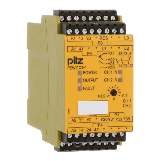
Page 16: Operation
Supply voltage is present. CH.1 IN Channel 1 safety contacts are closed. CH.2 IN Channel 2 safety contacts are closed. OUTPUT Safety contacts are closed and semiconductor output Y32 carries a high signal. Operating Manual PSWZ X1P | 16 21005-EN-11... -
Page 17: Fault Indicators
Contact malfunctions: If the contacts have welded, reactivation will not be possible after the input circuit has opened. When exceeding the simultaneity time the safety contacts 13-14, 23-24 remain open. Dimensions in mm * with spring-loaded terminals Operating Manual PSWZ X1P | 17 21005-EN-11... -
Page 18: Technical Details
Pulse duration, feedback loop 0,1 s 0,1 s Reset input 777949 777950 Low signal < 5 V < 5 V High signal > 15 V > 15 V Current 20 mA 20 mA Operating Manual PSWZ X1P | 18 21005-EN-11... - Page 19 In accordance with the standard EN 60947-5-1 EN 60947-5-1 Utilisation category of safety con- tacts AC15 at 230 V 230 V Max. current DC13 (6 cycles/min) at 24 V 24 V Max. current Operating Manual PSWZ X1P | 19 21005-EN-11...
- Page 20 1.500 ms After power on max. 2.200 ms 2.200 ms Delay-on de-energisation After motor on max. 170 ms 170 ms Recovery time at max. switching frequency 1/s After motor on 2.200 ms 2.200 ms Operating Manual PSWZ X1P | 20 21005-EN-11...
- Page 21 PPO UL 94 V0 PPO UL 94 V0 Front ABS UL 94 V0 ABS UL 94 V0 PPO UL 94 V0 PPO UL 94 V0 Connection type Screw terminal Screw terminal Mounting type plug-in plug-in Operating Manual PSWZ X1P | 21 21005-EN-11...
- Page 22 Max. measuring voltage 690 V 690 V Measuring voltage in accordance with UL 600 V 600 V Frequency range 0 - 3 kHz 0 - 3 kHz Input resistance 1.300 kOhm 1.300 kOhm Operating Manual PSWZ X1P | 22 21005-EN-11...
- Page 23 Min. current 0,01 A 0,01 A Max. current Max. power 1500 VA 1500 VA DC1 at 24 V 24 V Min. current 0,01 A 0,01 A Max. current Max. power 150 W 150 W Operating Manual PSWZ X1P | 23 21005-EN-11...
- Page 24 66 A²s Blow-out fuse, quick Blow-out fuse, slow Blow-out fuse, gG Circuit breaker 24 V AC/DC, characteristic B/C Conventional thermal current Contact material AgCuNi + 0,2 µm Au AgCuNi + 0,2 µm Au Operating Manual PSWZ X1P | 24 21005-EN-11...
- Page 25 Pollution degree Rated insulation voltage 690 V 690 V Rated impulse withstand voltage 6 kV 6 kV Protection type Housing IP40 IP40 Terminals IP20 IP20 Mounting area (e.g. control cab- inet) IP54 IP54 Operating Manual PSWZ X1P | 25 21005-EN-11...
- Page 26 50 - 60 Hz 50 - 60 Hz Residual ripple DC 160 % 160 % 160 % Max. inrush current at UB 10 A 10 A 10 A Duty cycle 100 % 100 % 100 % Operating Manual PSWZ X1P | 26 21005-EN-11...
- Page 27 Number of output con- tacts Safety contacts (N/O), instantaneous Auxiliary contacts (N/C) 1 Max. short circuit current 1 kA 1 kA 1 kA Utilisation category In accordance with the standard EN 60947-4-1 EN 60947-4-1 EN 60947-4-1 Operating Manual PSWZ X1P | 27 21005-EN-11...
- Page 28 DC13 (6 cycles/min) at 24 V 24 V 24 V Max. current Utilisation category in ac- cordance with UL Voltage 240 V AC G. P. 240 V AC G. P. 240 V AC G. P. With current Operating Manual PSWZ X1P | 28 21005-EN-11...
- Page 29 2.200 ms 2.200 ms Supply interruption before de-energisation 20 ms 20 ms 20 ms Simultaneity, channel 1 and 2 max. Environmental data 787949 787950 787951 Climatic suitability EN 60068-2-78 EN 60068-2-78 EN 60068-2-78 Operating Manual PSWZ X1P | 29 21005-EN-11...
- Page 30 0,2 - 1,5 mm², 24 - 16 0,2 - 1,5 mm², 24 - 16 crimp connector Spring-loaded terminals: Terminal points per con- nection Stripping length with spring-loaded terminals 8 mm 8 mm 8 mm Operating Manual PSWZ X1P | 30 21005-EN-11...
-
Page 31: Safety Characteristic Data
A safety function's SIL/PL values are not identical to the SIL/PL values of the units that are used and may be different. We recommend that you use the PAScal software tool to calculate the safety function's SIL/PL values. Operating Manual PSWZ X1P | 31 21005-EN-11... -
Page 32: Supplementary Data
The service life graphs indicate the number of cycles from which failures due to wear must be expected. The wear is mainly caused by the electrical load; the mechanical load is negli- gible. Switching current (A) Fig.: Service life graphs at 24 VDC and 230 VAC Operating Manual PSWZ X1P | 32 21005-EN-11... - Page 33 To increase the service life, sufficient spark suppression must be provided on all relay con- tacts. With capacitive loads, any power surges that occur must be noted. With DC contact- ors, use flywheel diodes for spark suppression. Operating Manual PSWZ X1P | 33 21005-EN-11...
- Page 34 European Parliament and of the Council. The complete EC Declaration of Conformity is available on the Internet at www.pilz.com/support/downloads. Representative: Norbert Fröhlich, Pilz GmbH & Co. KG, Felix-Wankel-Str. 2, 73760 Ost- fildern, Germany Operating Manual PSWZ X1P...
- Page 35 We are represented internationally. Please refer to our homepage www.pilz.com for further details or contact our headquarters. Headquarters: Pilz GmbH & Co. KG, Felix-Wankel-Straße 2, 73760 Ostfildern, Germany Telephone: +49 711 3409-0, Telefax: +49 711 3409-133, E-Mail: info@pilz.com, Internet: www.pilz.com...
Need help?
Do you have a question about the PSWZ X1P and is the answer not in the manual?
Questions and answers