PICOTE MINI PUMP Owner's Operation & Safety Manual
Brush coating system
Hide thumbs
Also See for MINI PUMP:
- Operation & safety manual (34 pages) ,
- Operation & safety manual (34 pages)
Table of Contents
Advertisement
Quick Links
Advertisement
Table of Contents

Related Manuals for PICOTE MINI PUMP


Summary of Contents for PICOTE MINI PUMP
- Page 1 MINI PUMP PICOTE BRUSH COATING™ SYSTEM OPERATION & SAFETY MANUAL These instructions are for your personal safety. Always ensure that you have read and understood these instructions before using any of the Picote Brush Coating ™ System Range.
-
Page 2: Table Of Contents
Topic Page SAFETY INFORMATION & SYMBOLS ENVIRONMENTAL, TRANSPORT, STORAGE & DISPOSAL CE DECLARATION OF CONFORMITY WRC PRODUCT CERTIFICATE PICOTE MINI MILLER COATING PUMP MINI MILLER REQUIRED PARTS 10-11 PREPARING THE ORIGINAL PIPE FOR COATING COATING SYSTEM ASSEMBLY 12-16 THE PUMP... - Page 3 Personal Protective Equipment Always use Personal Protective Equipment when using the Picote Coating System, including suitable overalls / protective clothing & footwear and the following: Always wear suitable eye protection when using the Coating System to pre- vent coating resin or other dust from irritating your eyes.
- Page 4 Mini Coating Pump should be transported in car or other vehicle laid down and secured with ratchet straps to prevent any sudden movements or accidents caused by hard braking or accident. Never transport the pump unit locked on top of the Picote milling machine. In a case of accident, the locking system may fail.
-
Page 5: Wrc Product Certificate
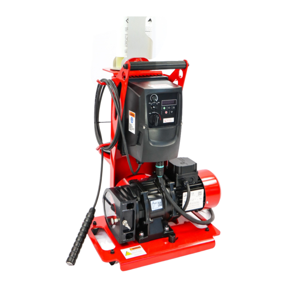
CE Declaration of Conformity We Picote Solutions Oy Ltd as the responsible manufacturer, declare that the following Picote Solutions Oy Ltd machine: Mini Coating Pump is of series production and Conforms to the following EU Directive: 2006/42/EC And is manufactured in accordance with the following standards or standardised documents:... - Page 6 Picote Mini Miller Coating Pump Intended Use General Description This machine is intended for the following uses: Power Cord Resin Supply Hose Coating pipes from DN32-200 / 1. ’’- 8’’ Delivery Hose Cleaning sewers and drains with degreaser. Motor Resin Cup Location Always follow the manufacture’s instructions when...
-
Page 7: Mini Miller 8/17
230V:1.2kW 59.5lb When is use, always lay the machine down horizontally on the floor as shown above. When not in use, some non-hazardous Picote Flexible Shaft Lubricant might leak from the hand guard. VOLTAGE POWER SUPPLY Ensure that the supply voltage is correct. The volt-... -
Page 8: Required Parts
Required Parts First make sure you have all the required parts. PRODUCT NUMBER DESCRIPTION INFORMATION PRODUCT NAME 1. MINI MILLER COATING PUMP 2220100001 Mini Miller Coating Pump Hoses, brushes & other parts EU 230v sold separately Mini Miller Coating Pump UK, 2220100002 US 110v 2. - Page 9 For DN150/6’’ drain 2120000220 For DN200/8’’ drain Extra stopper to secure brush 900000338 Brush Stopper 5. PICOTE 100% SOLIDS EPOXY 2110001001 Picote Dual Color Epoxy Kit, 6 Cartridge Kit (3 White, 3 12lbs 5oz Dark Grey) with 8 Tips & 3...
- Page 10 Substrate preparation is one of the most crucial steps in the coating process as specialized coating resin is designed to bond to the host pipe. Be sure to remove all scale, grease, dust and any other debris com- pletely from the pipe before coating. If coating plastic pipe be sure to abrade thoroughly with Picote Smart Cutter grinding panels.
- Page 11 STEP 3 The pipe MUST be dry before continuing with the coating setup. Use the Picote Heater to expedite the process. Once the original pipe is clean, move on to the...
-
Page 12: Coating System Assembly
COATING SYSTEM ASSEMBLY >THE PUMP Required Tools & Parts SCISSORS NUT DRIVER 7mm PICOTE HOSE LUBE RESIN CUP RED SUPPLY HOSE BLACK DELIVERY HOSE 11mm & 13mm HOSE CLAMPS BEFORE BEGINNING ASSEMBLY DANGER Risk of serious injury from rotating parts! •... - Page 13 Coating System Assembly >The Pump STEP 1 Cut the Resin Pump Supply Hose in between 248mm to 254mm (9.¾” to 10”). Ensure the ends are squared. 248mm to 254mm / 9.¾” to 10” Prepare the Hose Connectors and Hose Clamps to be inserted into Resin Supply STEP 2 Hose.
- Page 14 Coating System Assembly >The Pump STEP 4 With hose clamps facing outward, insert the connector into bottom of the housing key-way. STEP 5 Push hose into housing and slowly rotate the pump rotor clockwise manually while feeding the hose into place. Tip! Silicone grease will make the process easier. STEP 6 Slide second connector into the top key-way.
- Page 15 Coating System Assembly >The Pump STEP 7 Ensure hose clamps are facing inward and outward for easy access if required. Apply a small amount of a silicone grease to the underside of the hose at the bottom of STEP 8 the housing.
- Page 16 Coating System Assembly >The Pump STEP 10 Cut a 1.2m or 47” piece of the black Delivery Hose to be used as a supply hose extension. One end will require a 45 degree angle and the other should be a square cut. STEP 11 Attach the square end of the hose to the top hose connector on pump using a small hose clamp.
-
Page 17: The Brushes
COATING SYSTEM ASSEMBLY >Brushes Before Beginning Assembly Required Tools & Parts • Have extra brush stoppers and hose BRUSHES (1 or 2) connectors available. BRUSH STOPPER Use angle grinder or portable band saw • SLEEVE BEARING to cut Mini Miller shaft if necessary. Have a roll of duct tape available. - Page 18 Coating System Assembly >Brushes Select the appropriate brush size for the pipe. Always use a brush one pipe size larger STEP 1 than the pipe to be coated. Note: Although one brush can be used in straight pipe, dual brushes are required for pipes with bends or transitions.
- Page 19 Coating System Assembly >Brushes The larger of the two brushes will be the brush at the tip of the shaft and is used for finishing the resin. The closest brush helps to spread the resin and stabilize the brush set during coating. STEP 3 Slide the larger brush onto the shaft followed by the supplied brush stopper.
-
Page 20: Delivery Hose & Camera
COATING SYSTEM ASSEMBLY >Delivery Hose & Camera Required Tools & Parts DELIVERY HOSE DUCT TAPE CAMERA NUT DRIVER SCISSORS 11mm CLAMP... - Page 21 Coating System Assembly >Delivery Hose & Camera When you are pulling the delivery hose from the roll, always pull from the center. This will keep the hose from getting tangled and messy. STEP 1 Pulling from the center of the delivery hose roll, attach the delivery hose 5-7cm / 2-3’’ behind the sleeve bearing with duct tape.
- Page 22 Coating System Assembly >Delivery Hose & Camera Once the brush is in full view on the screen, tape the camera head from the very end all STEP 3 the way to the end of the camera spring. This will ensure the camera spring and con- nectors inside stay clean during the process.
- Page 23 Coating System Assembly >Delivery Hose & Camera With the pump and miller positioned as close to the opening as possible, cut off the STEP 6 delivery hose (square cut) and attach to the bottom connector on the pump. Secure with a hose clamp. Once the Delivery Hose &...
-
Page 24: Preparing The Resin
PREPARING THE RESIN Required Tools & Parts Before Beginning Preparation In case of spills or accidents have plenty of • DUAL COLOR 100% SOLIDS rubber gloves, towels, chemical spill kit and EPOXY acetone readily available. Be sure to prepare all cartridges before •... - Page 25 Preparing The Resin Resin Calculator Use the resin calculator to determine how much resin will be needed to complete all necessary coats. Refer to the chart below for recommended number of coats. To receive resin calculator, plea- se send a request to support@picotesolutions.com. PIPE DIAMETER RECOMMENDED •...
- Page 26 Preparing The Resin To avoid contact with resin on skin, wear at least two pairs of safety STEP 2 gloves. The top pair will be removed during the cleanup process, leaving you with a clean pair of gloves on. STEP 3 There are 4 stages to setting up the resin cartridge.
- Page 27 Preparing The Resin Attach the static mixing tip and secure with the nut. STEP 4 Once the mixing tip and nut are securely fastened, insert the Epoxy Cartridge into the Smart Mixer. Now change the speed dial on the Smart Mixer to the 4th setting. Feather the trigger to allow the pistons to seat properly and evenly on the back of the car- STEP 5 tridge.
- Page 28 The Picote Delivery Hose Lube should added to a spray bottle to be easily applied to the outside of the line set.
- Page 29 Operating The Coating System Watch the CCTV screen for the resin flow. Note: it may be difficult to see the flow of STEP 2 resin if the camera is turned upside-down. Watch closely and move the camera back and forth if necessary to check for resin flow. Once resin can be seen flowing stop the pump and turn the variable speed dial down STEP 3 to the appropriate speed for the pipe diameter.
- Page 30 Average coat thickness is 0.7 to 0.8 mm. Carefully inspect that the resin covers the pipe everywhere. Be especially careful around bends. Once first coat is complete, apply heat after 20 minutes (Picote Heater) to the pipe before STEP 7 starting the next coat to speed up dry time.
- Page 31 Operating The Coating System STEP 8 If the next coat is applied after 24 hours, the original coat will need to be abraded with a Smart Cutter first to make sure that the layers bond well. Dual Color Method. Apply over existing color with new color. Verify that resin has been STEP 9 applied everywhere.
- Page 32 CLEANING UP THE COATING SYSTEM Required Tools & Parts Before Beginning Cleaning Process SCISSORS ACETONE In case of spills or accidents have plenty of • rubber gloves, towels, chemical spill kit and RAGS acetone readily available. Have buckets ready for cleaning the brush- •...
- Page 33 Cleaning Up The Coating System When you have finished coating, turn the pump rotation to reverse. This will pull the STEP 1 resin back to the cup and reduce dripping resin during the cleaning process. When the resin stops dripping, put the brushes in a bucket of Acetone. Cover the opening and run brushes for a short time to rinse off resin.
- Page 34 Cleaning Up The Coating System Stop the pump from spinning in reverse and shut the system down completely. Isolate STEP 4 the power supply. Remove cartridge from the Smart Mixer. Recap for later if there is unused material in the cartridge STEP 5 Wipe down the delivery hose so as not to make a mess and remove the pump hose from the housing.
- Page 35 Cleaning Up The Coating System STEP 7 With the entire hose set removed from the pump, cut away the hose connectors and clamps for reuse STEP 8 Remove hose clamps and carefully cut away hoses and dispose of them. STEP 9 Hose connectors can be cleaned with acetone and a small wire brush or cotton swab, or they can be allowed to cure and drilled out later.
- Page 36 Cleaning Up The Coating System STEP 10 Empty any remaining Epoxy in the resin cup into the trash can. Then wipe the container clean with acetone so that it can be used again later. If drilling, clamp the connector in a vise or hold tightly with locking pliers. Carefully STEP 11 drill the hardened resin out of the center entirely.
-
Page 37: Curing & Additional Coats
CURING & ADDITIONAL COATS CURING During the curing process, it is very impoprtant to prevent any dirt, debris or water from getting into the pipe. The pipe must stay clean and dry during the entire coating and curing process. Water can keep the resin from bonding properly. The resin is ready for additional coats once the surface is dry to touch. - Page 38 PICOTE DUAL COLOR EPOXY RESIN INFORMATION PICOTE 100% SOLIDS EPOXY Mixing ratio 2:1 / Pot life about 25 min Package Sizes: Cases contain 3 white and 3 dark gray cartridges each with 900ml of epoxy inside. Re-coat Restore flow - 2.5hrs @ 70F/21°C / - 4hrs.
-
Page 39: Maintenance
CARING FOR THE FLEXIBLE SHAFT (Mini Miller) The flexible shaft is pre-treated with Picote Flexible Shaft Lubricant and the casing replaced prior to ship- ping. Always inspect the condition and apply oil between the flexible shaft and its outer casing when re- quired. - Page 40 MACHINE MAINTENANCE MAINTENANCE PROGRAM Months Maintenance task Tightness of motor fixing Tightness pump assembly fixing Condition of pump assembly Condition of rollers Condition of frame & quick locks Condition of electric components Clean resin stains Operation of Smart Mixer Condition of hose clamps Condition of hose connectors I: Inspect, fix or replace if needed.
-
Page 41: Error Code List
Troubleshooting flowchart— Mini & Maxi Coating Pump Check ON/OFF Test in different power Switch of Control Does it power up? source Does the Control Box power up? Press Hand Button, keep pressed during test Change the Control Box Check operation of motor Rotates, but not nor- Rotates Normally... - Page 42 Note: Following a trip, the drive cannot be immediately reset. A delay time is inbuilt, which al- lows the power components of the drive time to recover to avoid damage. dAtA-F Internal memory fault (IO) Press stop-key. If fault persists, consult Picote Solutions. dAtA-E Internal memory fault Press stop-key. If fault persists, consult Picote Solutions.
- Page 43 WARRANTY POLICY & PROCEDURE Limited Warranty: Picote warrants to the original End User that the Product purchased by such End User will operate in accordance with and substantially conform to their published specifications when shipped or otherwise delivered to the End User and for a period of one (1) year, except electric motors for which the warranty...
- Page 44 Your Reseller / Salesperson or Picote Solutions For Information and Support Email: sales@picotesolutions.com Picote offers a range of training options at our World- INNOVATIVE THINKING wide Training Centers in Anderson, SC, USA, Finland In Finland, Picote is a very well established and in our new training center in UK.
Need help?
Do you have a question about the MINI PUMP and is the answer not in the manual?
Questions and answers