
Related Manuals for dehn 105 525


Summary of Contents for dehn 105 525
- Page 1 Blitzschutz/Erdung Montageanleitung Fangstange www.dehn.de www.dehn.de Publication No. 1712 / Update 04.15 Mat-No. 3003808 © Copyright 2015 DEHN + SÖHNE...
-
Page 2: Table Of Contents
INHALTSVERZEICHNIS Anwendung ........................3 Fangstangen mit Betonsockel ..................4 Montage ........................4 2.1.1 Betonsockel ..........................4 Rohrfangstange/Fangstange ..................6 2.2.1 Ableitung ..........................6 Anpassung der Rohrfangstange/Fangstange bei Dachneigungen bis zu einem Nei gungswinkel von 10° ................... 8 2.3.1 Adaptereinstellung ........................8 Fangstangen für Metalldächer ..................9 Montage ........................ -
Page 3: Anwendung
1. Anwendung Die Fang stan ge freihstehend eig net sich zum Er rich ten von "Getrennten Blitzschutz Fangeinrich- tungen" nach DIN EN 62305-3 (VDE 0185-305-3). Beim Ein satz der Fang stan ge freistehend ist das "Schutzwinkelverfahren" an zu wen den. Der Schutz win kel α... -
Page 4: Fangstangen Mit Betonsockel
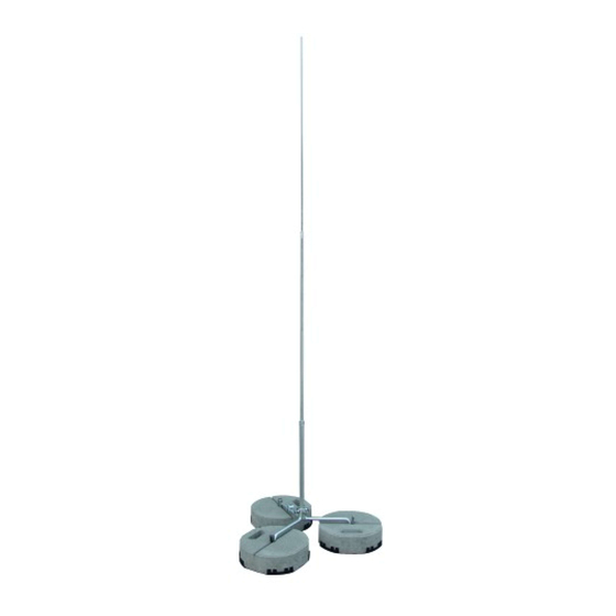
Rohrfangstange / Betonsockel Dreibeinstativ komplett Fangstange je Strebe Ø 22 / 16 / 10 mm Art.-Nr. 105 525 Art.-Nr. 103 233 Art.-Nr. 102 075 Art.-Nr. 105 501 Länge: 2500 mm Länge: 2500 mm 1x Betonsockel 8,5 kg Strebenlänge / Radius R = 320 mm Art.-Nr. - Page 5 Dreibeinstativ Aufnahme Dreibeinstativ / Verankerung Betonsockel 17 kg Betonsockel 8,5 kg Betonsockel Betonsockel Art.-Nr. 102 010 Art.-Nr. 102 075 Unterlegplatte Unterlegplatte Art.-Nr. 102 050 Art.-Nr. 102 060 Befestigungskeil Befestigungskeil Bild 3 Betonsockel...
-
Page 6: Rohrfangstange/Fangstange
Rohrfangstange/Fangstange Die Rohrfangstange/Fangstange wird in den Apdapter des Dreibeinstativs senkrecht ein geführt und mittels den vier Ar re tie rungsschrauben M10 (An zugs drehmo ment; 25 Nm) festgeschraubt. Dabei müssen die vier Sechs kant mut tern M 10 gegen den Ad ap ter gekontert werden (siehe Bild 4 auf Seite 7). - Page 7 Rohrfangstange / Fangstange Ø 22 / 16 / 10 (Alu, Niro/Al) Länge 2500 / 3000 / 3500 Arretierungsschraube M10 Stangenklemme Sechskantmutter M10 Dreibeinstativ Bild 4 Dreibeinstativ / Betonsockel / Rohrfangstange/Fangstange...
-
Page 8: Anpassung Der Rohrfangstange/Fangstange Bei Dachneigungen Bis Zu Einem Nei Gungswinkel Von 10
Anpassung der Rohrfangstange/Fangstange bei Dachneigungen bis zu einem Nei gungswinkel von 10° 2.3.1 Adaptereinstellung Die am Dreibeinstativ angebrachte Aufnahme ermöglicht die Montage von frei ste hen den Fangstangen mit einem Durch messer von 22 mm. Mit dem Adapter können Rohrfang stan gen/Fangstangen bei Dach- nei gun gen oder auch Geländeneigungen bis zu einem Neigungswinkel von 10°... -
Page 9: Fangstangen Für Metalldächer
3. Fangstangen für Metalldächer Montage Zur mechanischen Stabilisierung der Fangstange und den mög li chen Wind last be ein flus sun gen muss an jedes Stre ben ende des Strebengestells (Bohrung Ø 11mm) ein Dach lei tungs hal ter mon tiert werden (siehe Bild 6 auf Seite 10). - Page 10 Sechskantmutter M8 / 15 Nm z.B. Scheibe oder Klemmbock Strebengestell Bohrung, Ø 11 mm Strebenende Dachleitungshalter: Rundstehfalz, Art.-Nr. 223 010 oder Stehpfalz, Art.-Nr. 365 059 Sechskantmutter M16 / 70Nm Profilabstände 230 - 520 mm Strebengestell mit Dachleitungshalter, Strebengestell mit Dachleitungshalter, Stehfalz, Art.-Nr.
-
Page 11: Fangstange
Fangstange Die Rohrfangstange wird in den Apdapter des Stre ben ge stel les senkrecht ein geführt und mittels den vier Ar re tie rungsschrauben M8 (An zugs drehmo ment; 15 Nm) festgeschraubt. Dabei müssen die vier Sechs kant mut tern M8 gegen den Ad ap ter gekontert werden (siehe Bild 7 auf Seite 12). - Page 12 Rohrfangstange / Fangstange Ø 22 / 16 / 10 (Alu, Alu / Niro) Länge 2500 / 3000 / 3500 Arretierungsschraube M10 Sechskantmutter M10 Dachprofil, Typ: Rundstehfalz Bild 7 Strebengestell / Rohrfangstange...
-
Page 13: Anpassung Der Fangstange Bei Dachneigungen Bis Zu Einem Nei Gungswinkel Von 10
Anpassung der Fangstange bei Dachneigungen bis zu einem Nei gungswinkel von 10° 3.3.1 Adaptereinstellung Die am Strebengestell angebrachte Aufnahme ermöglicht die Montage von frei ste hen den Fangstangen mit einem Durch messer von 22 mm. Mit dem Adapter können Fang stan gen bei Dach nei gun gen oder auch Geländeneigungen bis zu einem Neigungswinkel von 10°... -
Page 14: Montage Unter Berücksichtigung Der Windzone / Windgeschwindigkeit
Die Dimensionierung / Auslegung der Fangstangen basiert auf der Berechnungsgrundlage DIN EN 1991-1-4 / NA (siehe Bild 9). Abweichungen sind möglich. Technische Spezifi kationen unserer Bauteile für eine statische Berechnung können angefordert werden. Die Gewährleistung von DEHN + SÖHNE ist gegeben, wenn die vorher genannten Angaben berücksichtigt und eingehalten werden. - Page 15 Notizen...
- Page 16 DEHN + SÖHNE Hans-Dehn-Str. 1 Tel. +49 9181 906-0 Überspannungsschutz GmbH + Co.KG. Postfach 1640 Fax +49 9181 906-1100 Blitzschutz/Erdung 92306 Neumarkt info@dehn.de Arbeitsschutz Germany www.dehn.de DEHN schützt.
- Page 17 Lightning protection/earthing Installation instructions Air-Termination Rod www.dehn.de Publication No. 1712 / Update 04.15 Mat-No. 3003808 © Copyright 2015 DEHN + SÖHNE...
- Page 18 CONTENTS Use ..........................3 Air-termination rods with concrete block..............4 Installation ........................4 2.1.1 Concrete block ..........................4 Tubular air-termination rod / air-termination rod ............6 2.2.1 Down conductor ........................6 Adjustment of the tubular air-termination rod / air-termination rod in case of roof inclinations up to an inclination angle of 10°...
-
Page 19: Use
1. Use Isolated air-termination rods are sui tab le for installing ”i so la ted air-terminations” in ac cor dance with IEC/EN 62305-3) When using isolated air-termination rods, the ”pro tec tive angle me thod” has to be applied. The protective angle α de pends on the class of LPS (lightning protection level) and the height of the isolated air-termination rod abo ve the reference plane. -
Page 20: Air-Termination Rods With Concrete Block
Concrete block Tripod isolated air-termination rod/ Air-termination rod per brace Ø 22 / 16 / 10 mm Part No. 105 525 Part No. 103 233 Part No. 102 075 Part No. 105 501 Length: 2500 mm Length: 2500 mm 1x concrete block 8.5 kg... - Page 21 adapter tripod tripod / bracing concrete block 17 kg concrete block 8,5 kg concrete block concrete block Part No. 102 010 Part No. 102 075 support plate support plate Part No. 102 060 Part No. 102 050 wedge wedge Figure 3 Concrete blocks...
-
Page 22: Tubular Air-Termination Rod / Air-Termination Rod
Tubular air-termination rod / air-termination rod The tubular air-termination rod / air-termination rod is vertically inserted into the adapter of the tripod and the four M10 locking screws are tightened (tightening torque of 25 Nm). The four M10 hexagon nuts have to be tightened against the adapter (see Figure 4 on page 7). 2.2.1 Down conductor The down conductor (round wire 8-10 mm) is connected via a rod clamp (positioned for transport) on the tripod and has to be connected to the next air-termination system or earth-termination system... - Page 23 tubular air-termination rod / air-termination rod Ø 22 / 16 / 10 (Al, StSt / AI) length 2500 / 3000 / 3500 M10 locking srew rod clamp M10 hexagon nut tripod Figure 4 Tripod / concrete block / tubular air-termination rod/air-termination rod...
-
Page 24: Adjustment Of The Tubular Air-Termination Rod / Air-Termination Rod In Case
Adjustment of the tubular air-termination rod / air-termination rod in case of roof inclinations up to an inclination angle of 10° 2.3.1 Adjustment of the adapter Isolated air-termination rods with a diameter of 22 mm can be inserted in the adapter on the tripod. This adapter compensates tubular air-termination rods / air-termination rods in case of roof inclinations or slopes up to an inclination angle of 10°... -
Page 25: Air-Termination Rods For Metal Roof
3. Air-termination rods for metal roof Installation For mechanical stabilisation of the air-termination rod and protection against possible wind load ef- fects, a roof conductor holder has to be installed on every brace end of the brace frame (hole with a diameter of 11 mm) (see Figure 6 on page 10). - Page 26 M8 hexagon nut / 15 Nm e.g. flat washer or clamping frame brace frame hole, Ø 11 mm brace end roof conductor holder: round standing seam, Part No. 223 010 M16 hexagon nut / 70 Nm standing seam, Part No. 365 059 profile clearances 230 - 520 mm brace frame with roof conductor holder, brace frame with roof conductor holder,...
-
Page 27: Air-Termination Rod
Air-termination rod The tubular air-termination rod is vertically inserted into the adapter of the brace frame and the four M8 locking screws are tightened (tightening torque of 15 Nm). The four M8 hexagon nuts have to be tightened against the adapter (see Figure 7 on page 12). 3.2.1 Discharge of lightning current The air-termination rod is electrically connected to the metal roof via the brace frame and the four conductor holders / clamps. - Page 28 tubular air-termination rod / air-termination rod Ø 22 / 16 / 10 (Al, AI / StSt) length of 2500 / 3000 / 3500 M10 locking screw M10 hexagon nut roof profile, type: round standing seam Figure 7 Brace frame / tubular air-termination rod...
-
Page 29: Adjustment Of The Air-Termination Rod In Case Of Roof Inclinations Up To
Adjustment of the air-termination rod in case of roof inclinations up to an inclination angle of 10° 3.3.1 Adjustment of the adapter Isolated air-termination rods with a diameter of 22 mm can be inserted into the adapter attached to brace frame. This adapter compensates air-termination rods in case of roof inclinations or slopes up to an inclination angle of 10°... -
Page 30: Installation With Regard To The Wind Zone / Wind Speed
Figure 9 Wind zones in Germany (source: EN 1991-1-4/NA, annex NA.A: Wind zone map) The air-termination rods are dimensioned based on EN 1991-1-4 (see Figure 9). Technical specifi cations for our components for performing static calculations are available on request. DEHN + SÖHNE only assumes warranty if the information provided above is observed. - Page 31 Notes...
- Page 32 DEHN + SÖHNE Hans-Dehn-Str. 1 Tel. +49 9181 906-0 Surge Protection GmbH + Co.KG. Postfach 1640 Fax +49 9181 906-1444 Lightning Protection 92306 Neumarkt export@dehn.de Safety Equipment Germany www.dehn.de DEHN protects.
Need help?
Do you have a question about the 105 525 and is the answer not in the manual?
Questions and answers