Vaisala CARBOCAP GMW80 Series User Manual
Carbon dioxide, humidity, and temperature transmitters
Hide thumbs
Also See for CARBOCAP GMW80 Series:
- User manual (42 pages) ,
- User manual (26 pages) ,
- Quick manual (18 pages)

Related Manuals for Vaisala CARBOCAP GMW80 Series


Summary of Contents for Vaisala CARBOCAP GMW80 Series
- Page 1 M211748EN-G User Guide Vaisala CARBOCAP® Carbon Dioxide, Humidity, and Temperature Transmitters GMW80 Series...
- Page 2 English versions are This product contains software developed applicable, not the translations. by Vaisala or third parties. Use of the The contents of this document are subject software is governed by license terms and to change without prior notice.
-
Page 3: Table Of Contents
Table of contents Table of contents About this document..................5 Version information..................5 Related manuals....................5 Documentation conventions................5 Trademarks......................6 Patent notice..................... 6 Product overview.................... 7 Introduction to GMW80 series................ 7 2.1.1 Transmitter parts..................9 2.1.2 GMW87 and GMW88 transmitter parts..........10 Display.......................12 2.2.1 Startup screens..................13... - Page 4 GMW80 Series User Guide M211748EN-G Technical data....................43 Specifications....................43 Spare parts and accessories................. 46 Dimensions...................... 47 Appendix A: Modbus reference..............49 Function codes....................49 Data encoding....................49 A.2.1 32-bit floating point format..............49 A.2.2 16-bit integer format................50 Modbus registers....................50 A.3.1 Measurement data registers..............
- Page 5 List of figures List of figures Figure GMW80 series transmitter parts..............9 Figure 2 GMW80 series component board parts............ 10 Figure 3 GMW87 transmitter parts................11 Figure 4 GMW88 transmitter parts................12 Figure 5 Example startup screens................13 Figure 6 Example measurement screens..............14 Figure 7 Example error message on display.............14 Figure 8...
- Page 6 GMW80 Series User Guide M211748EN-G List of tables Table 1 Document versions (English)................5 Table 2 Applicable patents or applications..............6 Table 3 GMW80 series transmitters................7 Table 4 Relay setpoints....................15 Table 5 Troubleshooting table, transmitters with analog output......39 Table 6 Troubleshooting table, transmitter model GMW87........41 Table 7 GMW80 models....................43...
-
Page 7: About This Document
Chapter 1 – About this document 1. About this document 1.1 Version information This document provides detailed instructions for using and maintaining Vaisala CARBOCAPâ Carbon Dioxide, Temperature, and Humidity Transmitter Series GMW80 devices. Table 1 Document versions (English) Document code Date Description... -
Page 8: Trademarks
GMW80 Series User Guide M211748EN-G 1.4 Trademarks Vaisalaâ, CARBOCAPâ, and INTERCAPâ are registered trademarks of Vaisala Oyj. Modbusâ is a registered trademark of Schneider Automation Inc. All other product or company names that may be mentioned in this publication are trade names, trademarks, or registered trademarks of their respective owners. -
Page 9: Product Overview
Chapter 2 – Product overview 2. Product overview 2.1 Introduction to GMW80 series Vaisala GMW80 series CARBOCAPâ carbon dioxide, humidity, and temperature transmitters are wall-mount transmitters designed to fulfill the needs for CO measurements in standard demand controlled ventilation applications. The following table lists the GMW80 series transmitters and their features. - Page 10 GMW80 Series User Guide M211748EN-G The CO measurement is based on the Vaisala proprietary CARBOCAPâ sensor, which uses a novel, silicon-based microchip emitter instead of an incandescent light bulb. The internal reference in the CO sensor guarantees the best stability and operation also in constantly occupied buildings without frequent readjustments.
-
Page 11: Transmitter Parts
Chapter 2 – Product overview 2.1.1 Transmitter parts Figure 1 GMW80 series transmitter parts Opening tab Screw terminals. The wiring information is marked on the mounting base next to the terminals. Barrier to prevent the cable from being routed below the GM10 measurement module. The area to avoid is marked NO CABLES on the mounting base. -
Page 12: Gmw87 And Gmw88 Transmitter Parts
Figure 2 GMW80 series component board parts Pins connecting the transmitter cover to the screw terminals when the transmitter cover is in place Vaisala INTERCAPâ humidity sensor (on models with the letter R) Pt1000 temperature sensor for passive temperature measurement (on models with the letter P) -
Page 13: Figure 3 Gmw87 Transmitter Parts
Chapter 2 – Product overview Figure 3 GMW87 transmitter parts DIP switches for Modbus settings Screw terminals. The screw terminal block is detachable for easy installation. Transmitter cover with captive screws (4 pcs) GM10 carbon dioxide measurement module Mounting base Screw holes for mounting on top and bottom of mounting base (2 screws, Ø 3.5 mm) Alternative lead-through for wiring through the back (break seal, transfer cable gland here and seal cable gland hole on bottom of transmitter) Cable gland for leading the input/output cable (Ø... -
Page 14: Display
GMW80 Series User Guide M211748EN-G Figure 4 GMW88 transmitter parts GM10 carbon dioxide measurement module Screw terminals. The wiring information is printed on a label on the mounting base. Transmitter cover with captive screws (4 pcs) Mounting base Screw holes for mounting on top and bottom of mounting base (2 screws, Ø 3.5 mm) Alternative lead-through for wiring through the back (break seal, transfer cable gland here and seal cable gland hole on bottom of transmitter) Cable gland for leading the input/output cable (Ø... -
Page 15: Startup Screens
Chapter 2 – Product overview 2.2.1 Startup screens When a GMW80 series transmitter with a display is powered on, it shows a sequence of information screens. The screens are shown for a few seconds each. Figure 5 Example startup screens The first screen shows the following information: •... -
Page 16: Error Messages
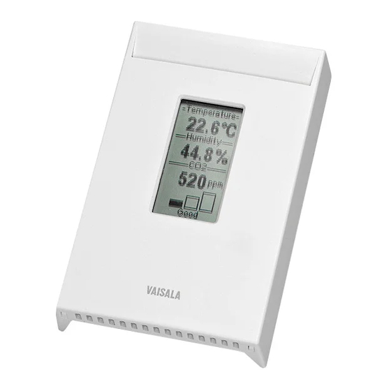
GMW80 Series User Guide M211748EN-G Figure 6 Example measurement screens Note that temperature measurement data is displayed in Celsius scale only. 2.2.3 Error messages If there is a problem with measurement, affected readings are replaced with stars. The alarm indicator and an error message will also appear on the screen. If more than one error is active, the display will cycle through the errors, showing each error for a few seconds. -
Page 17: Relay
Chapter 2 – Product overview 2.3 Relay Transmitter model GMW84S has one SPST-NO relay (max. 50 VDC / 50 VAC, 500 mA) that is activated when the measured CO level rises above the setpoint. When the relay is active (contact is closed), a green LED is lit on the transmitter cover. Figure 8 Relay indicator LED on GMW84S Relay setpoint is set using a rotary switch on the component board. -
Page 18: Co 2 Level Indicator Leds
GMW80 Series User Guide M211748EN-G Switch position Setpoint in ppm CO 900 ppm 1000 ppm 1200 ppm 1400 ppm 1600 ppm 1800 ppm 2000 ppm A hysteresis of 50 ppm is applied to prevent the relay from switching back and forth when the measured value is near the setpoint value. -
Page 19: Analog Output Overrange Behavior
Chapter 2 – Product overview Transmitter model GMW83A has indicator LEDs for the measured CO level on the front cover. The LEDs provide a visual indication of the measured CO level to the occupant of the monitored space. The LEDs are lit as follows: •... -
Page 20: Figure 12 Overrange Behavior Of Co 2 Measurement With 0
GMW80 Series User Guide M211748EN-G Negative ppm values cannot physically exist but the behavior of the output is defined to account for cases where a low CO reading, combined with sensor drift, could cause a negative result. Output Error level 11.0 Output clipping limit 10.0... -
Page 21: Figure 13 Overrange Behavior Of Active Temperature Measurement
Chapter 2 – Product overview Output Error level 11.0 Output clipping limit 10.0 Scaled output range: 0 ... 10 V 0 ... 50 ºC T (ºC) -2.5 52.5 Figure 13 Overrange behavior of active temperature measurement Passive temperature measurement (reading the Pt1000 resistor) is not affected by the overrange behavior or the error state. -
Page 22: Safety
GMW80 Series User Guide M211748EN-G Output Error level 11.0 Output clipping limit 10.0 Scaled output range: 0 ... 10 V 0 ... 100 %RH Figure 14 Overrange behavior of relative humidity measurement The transmitter can measure humidities in excess of 100 %RH if the sensor element becomes wet due to condensation. -
Page 23: Regulatory Compliance
Chapter 2 – Product overview 2.7 Regulatory compliance GMW80 series complies with the following regulations: • RoHS Directive (2011/65/EU) • EMC Directive (2014/30/EU) • European Union CE marking The conformity is declared with using the following standards: • EN 50581: Technical documentation for the assessment of electrical and electronic products with respect to the restriction of hazardous substances. -
Page 24: Installation
GMW80 Series User Guide M211748EN-G 3. Installation 3.1 Selecting location Select a location that represents well the area of interest. Interior walls and columns are typically suitable locations. The installation height should be 1.2 ... 1.8 m (4 ... 6 ft). Figure 15 Examples of good installation locations Seal the cable opening when bringing a cable through the wall. -
Page 25: Opening And Closing The Transmitter
Chapter 3 – Installation • On points that experience excessive vibration. Figure 16 Examples of unsuitable installation locations 3.2 Opening and closing the transmitter GMW80 series transmitters are delivered from the factory with a pull tab that makes it easy to open the transmitter for installation. Note that the GMW87 and GMW88 models are opened and closed with 4 screws instead of an opening tab. -
Page 26: Installing The Mounting Base
GMW80 Series User Guide M211748EN-G 1. To open the transmitter after it has been installed: a. Loosen the locking screw if it has been installed. b. Use a flat screwdriver to push down the tab that holds the transmitter cover and mounting base together, and pull the top of the transmitter cover away from the mounting base. - Page 27 Chapter 3 – Installation 2. Use the mounting holes to attach the mounting base securely. Use at least two screws (not included). The mounting holes are suitable for the most common European, American, and Asian mounting boxes. The mounting base can be twisted on to pre- mounted screws.
-
Page 28: Installing Gmw87 And Gmw88
GMW80 Series User Guide M211748EN-G 3.4 Installing GMW87 and GMW88 Figure 17 Mounting GMW87 and GMW88 Cable gland for leading the input/output cable (Ø 4 ... 8 mm) inside the enclosure Alternative lead-through for wiring through the back (break seal and transfer cable gland to the threads on this lead-through) Wiring instructions label Mounting screws (2 pcs, Ø... -
Page 29: Wiring
With passive Pt1000 sensors the length of the cables affects the accuracy of the measurement reading, since the connection is susceptible to electrical interference. Vaisala recommends using shielded twisted pair cables, with the shield grounded. When using a shielded cable, do not connect the shield to the transmitter. -
Page 30: Figure 19 Locations Of The Breakaway Tabs
GMW80 Series User Guide M211748EN-G WARNING! Connect only de-energized wires. CAUTION! Do not route the cable through the area marked NO CABLES on the mounting base. That space is taken up by the CO measurement module when the transmitter cover is attached. You can also bring the cable to the housing from above or below, but you have to break off the small plastic tab that covers the hole on top or bottom of the housing. -
Page 31: Wiring Gmw83, Gmw83D, And Gmw83A
Chapter 3 – Installation Figure 20 Wiring from below with cable tie strain relief After completing the wiring, connect the transmitter body over the mounting base. Note that mounting bases are model-specific. 3.5.1 Wiring GMW83, GMW83D, and GMW83A Power supply GMW83 GMW83A 18 ... -
Page 32: Wiring Gmw83Rp And Gmw83Drp
GMW80 Series User Guide M211748EN-G 3.5.2 Wiring GMW83RP and GMW83DRP Power supply GMW83RP GMW83DRP 18 ... 35 VDC or 20 ... 30 VAC Controller T signal analog input (0 ... 10 V) 0...10 V RH signal analog input (0 ... 10 V) 0...10 V signal analog input 0...10 V... -
Page 33: Wiring Gmw84S
Chapter 3 – Installation 3.5.4 Wiring GMW84S Power supply GMW84S 18 ... 35 VDC or 20 ... 30 VAC Controller T signal analog input (4 ... 20 mA) 4...20 mA signal analog input (4 ... 20 mA) 4...20 mA Analog signal ground Relay_no Relay connections max 50 VDC / 50 VAC... -
Page 34: Wiring Gmw86P
GMW80 Series User Guide M211748EN-G 3.5.5 Wiring GMW86P GMW86P has two outputs for the CO signal: 4 ... 20 mA and 0 ... 10 V. You can use both outputs simultaneously but typically only one of them is needed. Note that they share a common minus terminal. -
Page 35: Wiring Gmw87
Chapter 3 – Installation 3.5.6 Wiring GMW87 Power supply GMW87 18 ... 35 VDC or 20 ... 30 VAC Controller isolated RS-485 RS-485 RSGND Leave the bottom terminal in GMW87 unconnected Figure 26 Wiring for GMW87 3.5.7 Wiring GMW88 Power supply GMW88 18 ... 35 VDC or 20 ... -
Page 36: Modbus Communication
GMW80 Series User Guide M211748EN-G 4. Modbus communication The Modbus variant used in GMW87 is Modbus RTU. For a list of the Modbus registers available in GMW87, see Modbus registers (page 50). You can use up to 8 transmitters on the same RS-485 line. You must configure each transmitter on the line to have a different Modbus address. -
Page 37: Figure 29 Modbus Device Address Dip Switch Example
Chapter 4 – Modbus communication Make selections with the DIP switches by sliding the DIP switch to the right (ON). Keep the other DIP switches on the left position (OFF). Setting Modbus device address with DIP switches Figure 29 Modbus device address DIP switch example The Modbus device address switches 32,... -
Page 38: Maintenance
46). 5.2 Replacing the CO measurement module (GM10) • GM10 spare part module (Vaisala item code GM10SP80) • Flat head screwdriver (for opening the transmitter) To replace the module: 1. Disconnect the transmitter body from the mounting base. 2. Locate the GM10 module on the transmitter. The module is a separate component board with a golden cuvette that contains the CARBOCAPâ... -
Page 39: Replacing The Intercap Humidity Sensor
Error state (page 42). 5.3 Replacing the INTERCAP humidity sensor • INTERCAPâ sensor (Vaisala item code 15778HM) • Flat head screwdriver (for opening the transmitter) CAUTION! To avoid contaminating or damaging the sensor: • Handle the sensor by its plastic frame. - Page 40 GMW80 Series User Guide M211748EN-G 6. Check the output of the transmitter (or the display if included on the model) to verify that the humidity measurement is working normally and the transmitter is not in the error state. For more information on the error state, see Error state (page 42).
-
Page 41: Troubleshooting
If you experience problems with GMW80 series transmitters, first see the following tables (for analog output and Modbus models) concerning the behavior and error indications of the transmitter. If you cannot locate the source of the error and return the transmitter to operational state, contact Vaisala. See Technical support (page 55). - Page 42 GMW80 Series User Guide M211748EN-G Problem or message Possible cause Solution reading is too low. The measured area contains • Use a portable instrument to materials that bind CO (such verify the CO reading at the as fresh concrete), producing a installation location.
-
Page 43: Table 6 Troubleshooting Table, Transmitter Model Gmw87
• Device is warming up, try again after 20 seconds non-zero status code returned • Power-cycle the transmitter by disconnecting the screw terminal block • Check that the GM10 module is properly attached • Contact Vaisala for a replacement GM10 module... -
Page 44: Error State
GMW80 Series User Guide M211748EN-G 6.2 Error state If the transmitter detects a serious hardware or software error, or the measured reading is well outside the scaled range, the analog outputs are set into a defined error level instead of the measured result. -
Page 45: Technical Data
Chapter 7 – Technical data 7. Technical data 7.1 Specifications Table 7 GMW80 models Model Measurements Output GMW86P Current and voltage output, Pt1000 +RH+T Voltage outputs, Pt1000 GMW83RP +RH+T Voltage outputs, Pt1000, Display with metric scale output GMW83DRP GMW83 Voltage outputs GMW83A Voltage outputs, CO indicator LEDs GMW83D... -
Page 46: Table 9 Gmw80 Compliance
Value/Description Response time (63 %) 60 s 7 min (GMW87 and GMW88) Carbon dioxide sensor Vaisala CARBOCAPâ GM10 Temperature Measurement range 0 … +50 °C (+32 ... +122 °F) Temperature sensor On P models: Pt1000 RTD Class F0.15 IEC 60751... -
Page 47: Table 11 Gmw80 Inputs And Outputs
Chapter 7 – Technical data Property Value/Description Storage temperature Models without display: –40 … +70 °C (−40 … +158 °F) Models with display: −30 … +70 °C (−22 … +158 °F) Table 11 GMW80 inputs and outputs Property Value/Description Supply voltage 18 …... -
Page 48: Spare Parts And Accessories
Display version: 124 g (4.37 oz) GMW87 and GMW88: 160 g (5.64 oz) 7.2 Spare parts and accessories Information on spare parts, accessories, and calibration products is available online at www.vaisala.com and store.vaisala.com. Item Item code module GM10SP80 INTERCAPâ sensor 15778HM... -
Page 49: Dimensions
Chapter 7 – Technical data 7.3 Dimensions All dimensions are in millimeters (mm). 60.3 81.1 25.9 Figure 31 Dimensions for GMW83, GMW83A, GMW83RP, GMW84, GMW84S, and GMW86P 60.3 81.1 25.9 Figure 32 Dimensions for GMW83D and GMW83DRP... -
Page 50: Figure 33 Dimensions For Gmw87 And Gmw88
GMW80 Series User Guide M211748EN-G SCREW TERMINAL WIRING 4 ... 20 mA 0 ... 10 V Figure 33 Dimensions for GMW87 and GMW88... -
Page 51: Appendix A: Modbus Reference
Appendix A – Modbus reference Appendix A. Modbus reference A.1 Function codes Table 13 Modbus function codes Function code (decimal) Function code (hexadecimal) Name Read Holding Registers 43/14 / 0E Read Device Identification A.2 Data encoding In the data registers, the numeric values are available in one or two formats with separate register addresses: 32-bit IEEE floating point format and/or 16-bit signed integer format. -
Page 52: 16-Bit Integer Format
GMW80 Series User Guide M211748EN-G A.2.2 16-bit integer format Table 14 Interpretation of 16-bit signed integer values Value Description 0000 … 7FFE Value in range 0 … 32766 8002 … FFFF Value in range -32766 … -1 (2’s complement) 8000 Value is not available The 16-bit integer value for measured temperature in Table 15 (page 50) is scaled to include... -
Page 53: Status Registers
: Status OK; if other values integer are returned, see Table 6 (page 41) Solving typical problems (page 39). 0201 Error code 32-bit Used by Vaisala Technical Support integer when solving device problems 0206 Temperature 16-bit 0000 : Status OK integer... -
Page 54: Device Identification Objects
Table 18 Device identification objects Object ID Object ID Object name Example contents (hexadecimal) VendorName “Vaisala” ProductCode "GMW80" MajorMinorVersion Software version (for example, "1.4.0") VendorUrl “https://www.vaisala.com/” ProductName "Vaisala CARBOCAP(R) Carbon Dioxide Transmitter GMW80" Transmitter serial number, e.g. SerialNumber "J1140501" Vaisala-specific device information object. -
Page 55: Modbus Communication Example
Appendix A – Modbus reference A.5 Modbus communication example Reading CO concentration value The device address used in the following example is 240 (F0 ). The values returned by the device differ depending on the ambient conditions. Your device might not return exactly the same values. Request Response Bytes on the line... -
Page 57: Maintenance And Calibration Services
Maintenance and calibration services Vaisala offers comprehensive customer care throughout the life cycle of our measurement instruments and systems. Our factory services are provided worldwide with fast deliveries. For more information, see www.vaisala.com/ calibration. • Vaisala Online Store at store.vaisala.com is available for most countries. - Page 60 www. v aisala.com...
Need help?
Do you have a question about the CARBOCAP GMW80 Series and is the answer not in the manual?
Questions and answers