
Related Manuals for MTS Sensors Level Plus Tank SLAYER


Summary of Contents for MTS Sensors Level Plus Tank SLAYER
- Page 1 Level Plus ® Magnetostrictive Liquid Level Transmitters with Temposonics Technology ® Tank SLAYER ® Operation Manual...
-
Page 2: Table Of Contents
Table of contents 1. Contact information ............................3 2. Terms and definitions ............................4 3. Introduction ..............................6 3.1 Purpose and use of this manual ................................6 3.2 Used symbols and warnings ..................................6 4. Safety instructions ............................. 6 4.1 Intended use ......................................6 4.2 Foreseeable misuse .................................... -
Page 3: Contact Information
Level Plus Tank SLAYER ® ® Operation Manual 1. Contact information United States General Tel: +1-919-677-0100 Fax: +1-919-677-2343 E-mail: info.us@mtssensors.com http://www.mtssensors.com Mailing and shipping address MTS Systems Corporation Sensors Division 3001 Sheldon Drive Cary, North Carolina, 27513, USA Customer service Tel: +1-800-633-7609 Fax: +1-800-498-4442 E-mail:... -
Page 4: Terms And Definitions
Level Plus Tank SLAYER ® ® Operation Manual 2. Terms and definitions GOVI (Gross Observed Volume of the Interface) 6A Heavy Oils The total volume of the tank occupied by the interface liquid. The ‘Generalized Crude Oils’, Correction of Volume to 60 °F against API GOVI is only given when measuring two liquids and is calculated by Gravity. - Page 5 Level Plus Tank SLAYER ® ® Operation Manual Strap Table A table of measurement correlating the height of a vessel to the Mass volume that is contained at that height. The transmitter can contain up The property of a body that causes it to have weight in a gravitational to 100 points.
-
Page 6: Introduction
1 to item 4 and only in conjunction with third-party devices is intended to provide information on mounting, installation and and components recommended or approved by MTS Sensors. As a commissioning by qualified service personnel according to IEC 60079-14 prerequisite of proper and safe operation, the product requires correct and local regulations or MTS trained service technicians. -
Page 7: Foreseeable Misuse
Level Plus Tank SLAYER ® ® Operation Manual 4.2 Foreseeable misuse 4.3 Installation, commissioning and operation Forseeable misuse Consequence 1. Wear proper personal protection equipment such as hard hat, Wrong sensor connection Possible damage to electronics safety shoes, flame resistant clothing, safety glasses, gloves, and See chapter 7 for Electrical hearing protection. -
Page 8: Product Overview
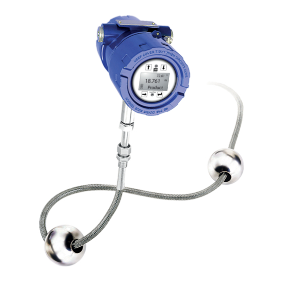
Level Plus Tank SLAYER ® ® Operation Manual 145 mm 75 mm (5.7 in.) (3 in.) 114 mm 109 mm (4.5 in.) (4.3 in.) 5. Product overview 5.1 Components 127 mm (5 in.) The Level Plus Tank Slayer Liquid-Level transmitter is a continuous The Level Plus Tank Slayer liquid level transmitter consists of... - Page 9 Level Plus Tank SLAYER ® ® Operation Manual Outer pipe configurations 206 mm (8.1 in.) 117 mm 75 mm The outer pipe is constructed of a variety of configurations. The Tank (4.6 in.) (3 in.) Slayer is available in a flexible hose. For other pipe options please ®...
-
Page 10: Accuracy
Level Plus Tank SLAYER ® ® Operation Manual Floats Tank Slayer transmitters offer numerous floats for different ® applications such as stainless steel and Hastelloy for both product ® level and interface level. To be able to accurately detect the interface level there needs to be a difference of at least 0.05 in specific gravities between the product and interface liquids. -
Page 11: Crn Specifications
Level Plus Tank SLAYER ® ® Operation Manual 5.5 CRN Specifications Below are the pressure calculations of the pressure ratings for ANSI Raised Face flanges available on the Tank SLAYER level transmitter ® according to flange and CRN calculations under ASME B31.3-2016. Do note, the maximum pressure rating for the flexible hose is 435 psi (30.0 bar) even though the calculations are higher. -
Page 12: Model Number Identification
Level Plus Tank SLAYER ® ® Operation Manual 5.6 Model number identification a Sensor model Process connection type T Tank Slayer Level Transmitter 1 NPT adjustable (1 in. only) ® 2 BSPP adjustable (1 in. only) b Output 6 150 lb. welded RF flange M Modbus 7 300 lb. - Page 13 Level Plus Tank SLAYER ® ® Operation Manual k Notified body o Length (no decimal spaces) C CEC (FMC) X Flexible sensor pipe: 1575…22000 mm (code as 01575 to 22000) E ATEX X Flexible sensor pipe: 62…866 in. F NEC (FM) (code as 06200 to 86600) X None p Special...
-
Page 14: Technical Data
Level Plus Tank SLAYER ® ® Operation Manual 5.7 Technical data Level Output Measured Variable Product level and interface level Output Signal /Protocol Modbus RTU, DDA, Analog (4…20 mA), HART ® 1575…22000 mm (62…866 in.) (order length equals the measurement range plus the inactive zone / Order Length contact factory for longer lengths) Inherent Accuracy... -
Page 15: Installation And Mounting
Level Plus Tank SLAYER ® ® Operation Manual 6. Installation and mounting 1. Consult chapter 4.3 before starting. 2. Perform steps 1-10 in chapter 8.4.1 for Modbus or DDA. Perform 6.1 Training steps 1-9 in chapter 8.4.2 for Analog. 3. Remove the stop collar. With assistance, feed the flexible hose Warning: through the hole of the removed tank flange until the flange When the pipe/hose of the LP-Series level transmitter is installed or... -
Page 16: Mounting
Level Plus Tank SLAYER ® ® Operation Manual 6.5 Mounting Flexible hose The method of mounting the transmitter is dependent on the vessel or tank in which it is being used, and what type of transmitter is being mounted. There are two typical methods for mounting; threaded flange mounting and welded flange mounting. -
Page 17: Electrical Connections
Level Plus Tank SLAYER ® ® Operation Manual 7.3 Industrial topologies There are four topologies described and illustrated below. However, the daisy chain topology is not recommended by MTS. Welding sleeve Point-to-point 28.6 mm (1.13 in.) dia Welded flange The point-to-point topology consists of having only one device on the loop as shown in Fig. -
Page 18: Cable Recommendations
Level Plus Tank SLAYER ® ® Operation Manual Tree alignment 7.4 Cable recommendations The tree topology is very similar to the bus with spurs topology with the main difference of having a common junction box for all of the Refer to ‘Table 2’ below for general requirements of cable types for the transmitters as shown in Fig. -
Page 19: Grounding
Level Plus Tank SLAYER ® ® Operation Manual 7.6 Grounding 7.7 Safety barriers 7.6.1 Safety grounding Refer to Table 3 for entity parameters and Table 4 for example safety barriers Warning: Grounding the transmitter through a threaded conduit connection Entity parameters does not meet the requirements as a grounding of the sensor for Ui = 28 VDC safety. -
Page 20: Commissioning
Level Plus Tank SLAYER ® ® Operation Manual 8. Commissioning 8.4.1 Modbus or DDA 8.1 Training 1. Consult chapter 4.3 before starting. 2. Remove level transmitter from shipping container. Commissioning should only be conducted by qualified service 3. Remove bottom fixing nut, washer, spacer, and stop collar. personnel according to IEC 60079-14 or MTS trained service 4. -
Page 21: Maintenance
Level Plus Tank SLAYER ® ® Operation Manual 9. Maintenance 9.4.1 General purpose applications 9.1 Training 9.4.1.1 Perform Inspection suggested in chapter 9.3. Maintenance should only be conducted by qualified service personnel according to IEC 60079-14 and local regulations or MTS trained 9.4.1.2 service technicians. -
Page 22: Repair
Level Plus Tank SLAYER ® ® Operation Manual 10. Repair 10.4 Troubleshooting Symptom Possible cause Action 10.1 RMA policy No power Check voltage at Important: communication transmitter Contact Technical Support or Customer Service for assistance if with transmitter Wiring incorrect Reference installation you suspect that the transmitter is not working correctly. -
Page 23: Spare Parts
Level Plus Tank SLAYER ® ® Operation Manual 11. Spare Parts 12. Interface Below are the spare parts list for the LP-Series show as the display, Tank Slayer is available with multiple outputs including Modbus, ® electronic module, sensing element, and flexible hose. Please contact DDA, and HART . -
Page 24: Agency Information
Level Plus Tank SLAYER ® ® Operation Manual 13. Agency information 13.1 Approvals overview The Notified Body is designated in the 13 digit of the model number and the Protection Method is designated in the 14 digit of the model number. -
Page 25: Certificates
Level Plus Tank SLAYER ® ® Operation Manual Notified body Protection method Classification Standard N = NEPSI I = Instrinsic Safety Ex ia IIC T4 Ga/Gb GB 3836.1-2010 Ta = -50°C to 71°C IP65 GB 3836.4-2010 GB 3836.20-2010 F = Flameproof Ex db IIB+H2 T6…T3 Ga/Gb GB 3836.1-2010 Ta = -40°C to 71°C IP65... -
Page 26: Fm (Nec)
Level Plus Tank SLAYER ® ® Operation Manual 8 POINT TEXT R3.30 [.13] 13.3.1.2 Labels SIZE Level Plus Transmitter Level Plus Transmitter ® MTS Systems Corporation Sensors Division 3001 Sheldon Drive, Cary, N.C. 27513 APPROVED 28.70 [1.13] MTS Systems Corporation Sensors Division 3001 Sheldon Dr. - Page 27 Level Plus Tank SLAYER ® ® Operation Manual 13.3.1.3 Installation drawing Fig. 22: Intrinsically Safe FM installation drawing, Modbus and DDA, Page 1...
- Page 28 Level Plus Tank SLAYER ® ® Operation Manual Fig. 23: Intrinsically Safe FM installation drawing, Modbus and DDA, Page 2...
- Page 29 Level Plus Tank SLAYER ® ® Operation Manual Fig. 24: Intrinsically Safe FM installation drawing, HART , Page 1 ®...
- Page 30 Level Plus Tank SLAYER ® ® Operation Manual Fig. 25: Intrinsically Safe FM installation drawing, HART , Page 2 ®...
- Page 31 Level Plus Tank SLAYER ® ® Operation Manual 13.3.2 FM XP 13.3.2.2 Labels 13.3.2.1 Specific Conditions of Safe Use Level Plus Transmitter FM16US0242X MTS Systems Corporation Sensors Division 1. Warning: The equipment contains non-metallic enclosure and APPROVED 3001 Sheldon Drive, Cary, N.C. 27513 process parts.
- Page 32 Level Plus Tank SLAYER ® ® Operation Manual 13.3.2.3 Installation Drawing Fig. 30: Explosionproof, FM Installation Drawing, Modbus and DDA, Page 1...
- Page 33 Level Plus Tank SLAYER ® ® Operation Manual Fig. 31: Explosionproof, FM Installation Drawing, Modbus and DDA, Page 2...
- Page 34 Level Plus Tank SLAYER ® ® Operation Manual Fig. 32: Explosionproof, FM Installation Drawing, HART , Page 1 ®...
- Page 35 Level Plus Tank SLAYER ® ® Operation Manual Fig. 33: Explosionproof, FM Installation Drawing, HART , Page 2 ®...
-
Page 36: Fmc (Cec)
Level Plus Tank SLAYER ® ® Operation Manual 8 POINT TEXT 13.4 FMC 13.4.1.2 Labels SIZE 13.4.1 FMC IS ® Level Plus Transmitter 13.4.1.1 Specific conditions of safe use 1. When EPL Ga or Da is required, parts of the equipment containing MTS Systems Corporation light metals (Aluminum or Titanium) shall be protected from Sensors Division... - Page 37 Level Plus Tank SLAYER ® ® Operation Manual Level Plus Transmitter APPROVED MTS Systems Corp. Sensors Division 3001 Sheldon Drive, Cary, N.C. 27513 LPXXXXXXXXXXXXXXXXXXXX XXXXXXXXX XX-XX REFER TO INSTALLATION DWG #651543-2/651594-2 FOR CAUTION/WARNINGS WARNING: SUBSTITUTION OF COMPONENTS MAY IMPAIR INTRINSIC SAFETY Avertissement : Se référer au document DWG # 651543-2/651594-2 précautions d'installations ATTENTION : La substitution de composants peut compromettre la sécurité...
- Page 38 Level Plus Tank SLAYER ® ® Operation Manual 13.4.1.3 Installation Drawing Fig. 38: Intrinsically Safe FMC installation drawing, Modbus and DDA, Page 1...
- Page 39 Level Plus Tank SLAYER ® ® Operation Manual Fig. 39: Intrinsically Safe FMC installation drawing, Modbus and DDA, Page 2...
- Page 40 Level Plus Tank SLAYER ® ® Operation Manual Fig. 40: Intrinsically Safe FMC installation drawing, Modbus and DDA, Page 3...
- Page 41 Level Plus Tank SLAYER ® ® Operation Manual Fig. 41: Intrinsically Safe FMC installation drawing, HART , Page 1 ®...
- Page 42 Level Plus Tank SLAYER ® ® Operation Manual Fig. 42: Intrinsically Safe FMC installation drawing, HART , Page 2 ®...
- Page 43 Level Plus Tank SLAYER ® ® Operation Manual Fig. 43: Intrinsically Safe FMC installation drawing, HART , Page 3 ®...
- Page 44 Level Plus Tank SLAYER ® ® Operation Manual 13.4.2 FMC XP 13.4.2.2 Labels 13.4.2.1 Specific Conditions of Safe Use Level Plus Transmitter FM16CA0130X MTS Systems Corporation Sensors Division 1. Warning: The equipment contains non-metallic enclosure and APPROVED 3001 Sheldon Drive, Cary, N.C. 27513 INSTALL PER # # 651552-2/651595-2 process parts.
- Page 45 Level Plus Tank SLAYER ® ® Operation Manual 13.4.2.3 Installation drawing Fig. 48: Explosionproof, FMC Installation Drawing, Modbus and DDA, Page 1...
- Page 46 Level Plus Tank SLAYER ® ® Operation Manual Fig. 49: Explosionproof, FMC Installation Drawing, Modbus and DDA, Page 2...
- Page 47 Level Plus Tank SLAYER ® ® Operation Manual Fig. 50: Explosionproof, FMC Installation Drawing, Modbus and DDA, Page 3...
- Page 48 Level Plus Tank SLAYER ® ® Operation Manual Fig. 51: Explosionproof, FMC Installation Drawing, HART , Page 1 ®...
- Page 49 Level Plus Tank SLAYER ® ® Operation Manual Fig. 52: Explosionproof, FMC Installation Drawing, HART , Page 2 ®...
-
Page 50: Atex And Iecex
Level Plus Tank SLAYER ® ® Operation Manual Fig. 53: Explosionproof, FMC Installation Drawing, HART , Page 3 ®... - Page 51 Level Plus Tank SLAYER ® ® Operation Manual 13.5 ATEX/IECEx 13.5.1.2 Labels 13.5.1 ATEX/IECEx IS Level Plus Transmitter 13.5.1.1 Specific conditions of safe use 1. When EPL Ga or Da is required, parts of the equipment containing MTS Systems Corporation Sensors Division light metals (Aluminum or Titanium) shall be protected from 3001 Sheldon Dr.
- Page 52 Level Plus Tank SLAYER ® ® Operation Manual Level Plus Transmitter FM19ATEX0180X 2809 IECEx FMG 19.0036X MTS Systems Corporation Sensors Division 3001 Sheldon Drive, Cary, N.C. 27513 INSTALL PER DRAWING # 651543-3/651594-3 SUPPLY VOLTAGE: 28 VDC II 1/2 G Ex ia IIC T4 Ga/Gb Ta = -50°C TO +71°C ;...
- Page 53 Level Plus Tank SLAYER ® ® Operation Manual 13.5.1.3 Installation drawing Fig. 58: Intrinsically Safe ATEX / IECEx installation drawing, Modbus and DDA, Page 1...
- Page 54 Level Plus Tank SLAYER ® ® Operation Manual Fig. 59: Intrinsically Safe ATEX / IECEx installation drawing, Modbus and DDA, Page 2...
- Page 55 Level Plus Tank SLAYER ® ® Operation Manual Fig. 60: Intrinsically Safe ATEX / IECEx installation drawing, HART , Page 1 ®...
- Page 56 Level Plus Tank SLAYER ® ® Operation Manual Fig. 61: Intrinsically Safe ATEX / IECEx installation drawing, HART , Page 2 ®...
- Page 57 Level Plus Tank SLAYER ® ® Operation Manual 13.5.2 ATEX/IECEx XP 13.5.2.2 Labels 13.5.2.1 Specific Conditions of Safe Use Level Plus Transmitter FM19ATEX0179X MTS Systems Corporation IECEx FMG19.0037X 2809 Sensors Division 1. Warning: The equipment contains non-metallic enclosure and 3001 Sheldon Drive, Cary, N.C. 27513 U.S.A process parts.
- Page 58 Level Plus Tank SLAYER ® ® Operation Manual 13.5.2.3 Installation drawing Fig. 64: Flame Proof, ATEX and IECEx Installation Drawing, Modbus and DDA, Page 1...
- Page 59 Level Plus Tank SLAYER ® ® Operation Manual Fig. 65: Flame Proof, FM Installation Drawing, Modbus and DDA...
- Page 60 Level Plus Tank SLAYER ® ® Operation Manual Fig. 66: Flame Proof, ATEX and IECEx Installation Drawing, HART , Page 1 ®...
- Page 61 Level Plus Tank SLAYER ® ® Operation Manual Fig. 67: Flame Proof, ATEX and IECEx Installation Drawing, HART , Page 2 ®...
- Page 62 Level Plus Tank SLAYER ® ® Operation Manual 13.5.3 EC Declaration of conformity...
- Page 63 Level Plus Tank SLAYER ® ® Operation Manual...
- Page 64 MTS, Temposonics and Level Plus are registered trademarks of MTS Systems Corporation in the United States; MTS SENSORS and the MTS SENSORS logo are trademarks of MTS Systems Corporation within the United States. These trademarks may be protected in other countries. All other trademarks are the property of their respective owners. Copyright © 2020 MTS Systems Corporation. No license of any intellectual property rights is granted.
Need help?
Do you have a question about the Level Plus Tank SLAYER and is the answer not in the manual?
Questions and answers