Table of Contents
Advertisement
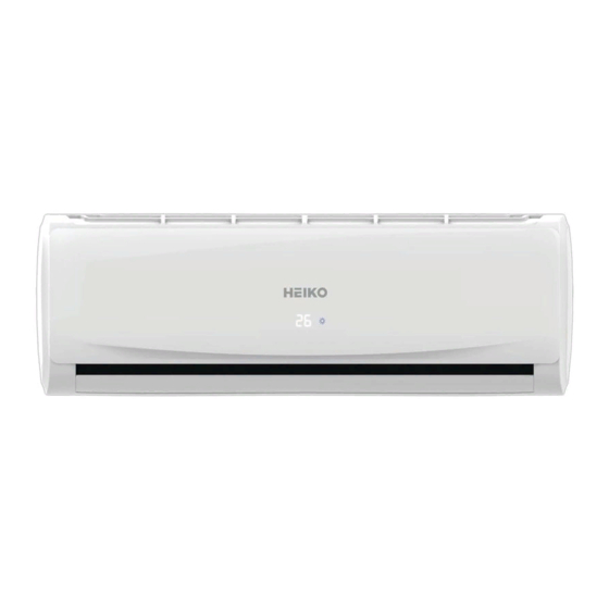
SERVICE MANUAL
Wall Mounted Type
T-Series
Model No.
JS035 - C1
WARNING
This service information is designed for experienced repair technicians only and is not designed for use by the general publi c.
It does not contain warnings or cautions to advise non-technical individuals of potential dangers in attempting to service a product.
Products powered by electricity should be serviced or repaired only by experienced professional technicians. Any attempt to s ervice or
Repair the product or products dealt with in this service information by anyone else could result in serious injury or death
Version:V1
Date:2020-2-20
Advertisement
Table of Contents

Related Manuals for Heiko JS035-C1


Summary of Contents for Heiko JS035-C1
- Page 1 SERVICE MANUAL Wall Mounted Type T-Series Model No. JS035 - C1 WARNING This service information is designed for experienced repair technicians only and is not designed for use by the general publi c. It does not contain warnings or cautions to advise non-technical individuals of potential dangers in attempting to service a product. Products powered by electricity should be serviced or repaired only by experienced professional technicians.
-
Page 2: Table Of Contents
Table fo contents Contents 1.Introduction ..................... 1 2.Features ....................7 3.Specifications ..................8 4.Sensors list ..................... 9 5.Pinping diagrams .................. 10 6.Printed circuit board connector wiring diagram ........11 7.Funcitions and control ................13 8.Dimensional drawings ................23 9.Center of gravity ................... 23 10. -
Page 3: Introduction
Introduction 1.Introduction 1.1 Safety Cautions Be sure to read the following safety cautions before conducting repair work. The caution items are classified into “Warning” and “Caution”. The “Warning” items are especially important since they can lead to death or serious injury if they are not followed closely. The “Caution” items can also lead to serious accidents under some conditions if they are not followed. - Page 4 Introduction 1.2.1 Caution in Repair Warning Be sure to disconnect the power cable plug from the plug socket before disassembling the equipment for a repair. Working on the equipment that is connected to a power supply can cause an electrical shook. If it is necessary to supply power to the equipment to conduct the repair or inspecting the circuits, do not touch any electrically charged sections of the equipment.
- Page 5 Introduction Warning Do not repair the electrical components with wet hands . Working on the equipment with wet hands can cause an electrical shock Do not clean the air conditioner by splashing water. Washing the unit with water can cause an electrical shock.
- Page 6 Introduction Warning Be sure to use an exclusive power circuit for the equipment, and follow the technical standards related to the electrical equipment, the internal wiring regulations and the instruction manual for installation when conducting electrical work. Insufficient power circuit capacity and improper electrical work can cause an electrical shock or fire. Be sure to use the specified cable to connect between the indoor and outdoor units.
- Page 7 Introduction Caution Installation of a leakage breaker is necessary in some cases depending on the conditions of the installation site, to prevent electrical shocks. Do not install the equipment in a place where there is a possibility of combustible gas leaks. If a combustible gas leaks and remains around the unit, it can cause a fire.
- Page 8 Introduction Caution Check to see if the parts and wires are mounted and connected properly, and if the connections at the soldered or crimped terminals are secure. Improper installation and connections can cause excessive heat generation, fire or an electrical shock. If the installation platform or frame has corroded, replace it.
-
Page 9: Features
Features 2.Features Easy Support Clip: It is more convenient for installation by extending space with additional support clip, meanwhile, saving time. Self Clean: With a new-generation hydrophilic foil, when the air conditioner in cooling or drying mode, the dust on evaporator will be taken away by condensed water flowing rapidly. A-PAM DC inverter: A-PAM inverter technology is the upgrade of 180°sine wave inverter, it adopts additional momental control to decrease the vibration in the low compressor frequency and also contribute to great energy... -
Page 10: Specifications
Specifications 3.Specifications NOMINAL DISTRIBUTION SYSTEM VOLTAGE Phase Frequency Voltage NOMINAL CAPACITY and NOMINAL INPUT Cooling heating 3.50 3.60 Capacity rated Btu/h 11940 12286 Power Consumption(Rated) 1.24 1.05 SEER/SCOP 6.1/A++ 4.0/A+ Annual energy consumption Moisture Removal m³/h 1.6*10 ﹣³ TECHNICAL SPECIFICATIONS Dimensions H*W*D 820×195×280... -
Page 11: Sensors List
Specifications TECHNICAL SPECIFICATIONS-PARTS cooling heating Type Cross flow fan Motor output Air flow rate(high) m³/h Speed(super/high/low) 1250/1150/850 1150/1050/750 Type ML fin-φ5HI-HX tube Heat exchanger Segment *stage*fitch 3*15*1.4 Air direction control Right,Left,Horizontal,Downward Removable/Washable/Mildew Proof Air filter Microcomputer Control Temperature control Remote controller model 0010401715Y Note: the data are based on the conditions shown in the table below Conversation formulae... -
Page 12: Pinping Diagrams
Piping diagrams 5.Pinping diagrams Domestic air conditioner... -
Page 13: Printed Circuit Board Connector Wiring Diagram
12) CN11 Connector for LEFT & RIGHT STEP motor Note: Other designations PCB(1) (Indoor Control PCB) 1) SWI Connector for Forced operation ON / OFF switch 2) FUSE1 Fuse 3.15A/250VAC UNIT MODEL PCB MODEL JS035-C1 0011800376AB (25) 325/498 UNIT MODEL DISPLAY MODEL JS035-C1 0011800387D... - Page 14 Dimensional drawings PCB(1) CN51 CN36 ‘’’ ‘’’ CN35 CN12 CN5’ CN11 CN23’ CN17 CN21 CN22’ Domestic air conditioner...
-
Page 15: Funcitions And Control
Dimensional drawings 7.Funcitions and control 7.1 Main functions and control specification 7.1.1 Automatic operation When the running mode is turned to automation after starting the system, the system will first determine the running mode according to the current room temperature and then will run according to the determined mode. - Page 16 Dimensional drawings Pn=(Nh_c- S_c) *10<40 PID control @2 Pn=(Nh_c- S_c) *10=<15 regular frequency and regular fan speed(EE) @1 When the starting ability is not the maximum frequency(EE), its maximum frequency limitation is calculated by the following equations: The frequency limitation=the maximum frequency(EE) * the rated frequency K of the indoor setting airflow speed Refrigeration mode: The indoor setting...
- Page 17 Dimensional drawings PIPING temp. THHOH3 THHOH2 THHOH1 THHOH0 set fan speed stop little low little stop If other conditions are satisfied, when the compressor stops, the indoor system will operate at a little speed. The indoor fan will stop when the coil temperature is below the THHOT0. 7.1.5 Strength operation The system enters the mode after receiving the ‘strength signal’.
- Page 18 Dimensional drawings 2.system /off timing: When the system is turned on, the timing indicator is lightened, the rest of the system will operated under a normal condition. When set time comes, the indicator light will be turned off and the system will be turned off. If you have set the dormant functions, the order of your settings will be operated according to the timing settings.
- Page 19 Dimensional drawings The temperature control doesn’t work. The test operation will be finished in 30 minutes. The test operation can be stopped by the relative commands from the remote control. 7.1.11 Abnormal operation of indoor system When the outdoor system operates, if the indoor system operation differs from the outdoor system, the abnormal operation malfunction will be reported.
- Page 20 Dimensional drawings * After the system enters the separate indoor system operation mode, the indoor system will operate according to the set mode and neglect the communication signals of the outdoor system. However, it has to send signals to the outdoor system. * Quitting condition: This mode can be quitted after receiving the quitting signal from the remote control or urgency system.
- Page 21 Dimensional drawings 109.51 15.97 103.462 15.22 3.38 97.779 14.56 3.26 92.437 13.93 3.15 87.415 13.34 3.04 82.691 12.77 2.94 78.248 12.23 2.84 74.067 11.71 2.74 70.133 11.22 2.65 66.43 10.76 2.56 62.943 10.31 59.659 9.89 56.566 9.49 53.651 50.904 8.74 48.314 8.39 45.872...
- Page 22 Dimensional drawings 66.3463 61.0123 56.0565 -1.64 1.52 62.8755 57.9110 53.2905 -1.62 1.51 59.6076 54.9866 50.6781 -1.60 1.49 56.5296 52.2278 48.2099 -1.58 1.47 53.6294 49.6244 45.8771 -1.56 1.46 50.8956 47.1666 43.6714 -1.54 1.44 48.3178 44.8454 41.5851 -1.51 1.42 45.8860 42.6525 39.6112 -1.49 1.40 43.5912...
- Page 23 Dimensional drawings 8.1371 7.8428 7.5522 -0.95 0.93 7.8299 7.5377 7.2498 -0.98 0.97 7.5359 7.2461 6.9611 -1.02 1.00 7.2546 6.9673 6.6854 -1.06 1.04 6.9852 6.7008 6.4222 -1.10 1.07 6.7273 6.4459 6.1707 -1.13 1.11 6.4803 6.2021 5.9304 -1.17 1.14 6.2437 5.9687 5.7007 -1.21 1.18 6.0170...
- Page 24 Dimensional drawings 1.7434 1.6021 1.4710 -2.88 2.67 1.6913 1.5528 1.4243 -2.92 2.71 1.6409 1.5051 1.3794 -2.97 2.75 1.5923 1.4592 1.3360 -3.02 2.80 1.5454 1.4149 1.2942 -3.07 2.84 1.5000 1.3721 1.2540 -3.12 2.88 1.4562 1.3308 1.2151 -3.17 2.93 1.4139 1.2910 1.1776 -3.22 2.97 1.3730...
-
Page 25: Dimensional Drawings
Dimensional drawings 8.Dimensional drawings 9.Center of gravity Domestic air conditioner... -
Page 26: Service Diagnosis
Service diagnosis 10. Service Diagnosis 10.1 Caution for Diagnosis The operation lamp flashes when any of the following errors is detected. 1. When a protection device of the indoor or outdoor unit is activated or when the thermistor malfunctions, disabling equipment operation. 2. - Page 27 Service diagnosis Outdoor EEPROM error Page .32 ■ ★ ■ The protection of IPM Page .36 □ ★ ★ Outdoor Overcurrent protection Malfunction AC electricity Page .37 ★ ★ ■ the outdoor model Communication fault between the IPM and Page.39 ■...
- Page 28 Service diagnosis Check the connector connection. Correct the connection Is it normal? Thermistor resistance check Replace the thermistor normal? Replace the indoor unit PCB Thermistor resistance check method: Remove the connector of the thermistor on the PCB, and measure the resistance of thermistor using tester.The relationship between normal temperature and resistance is shown in the value of indoor thermistor.
- Page 29 Service diagnosis 10.3.3 Indoor DC fan motor malfunction Indoor Display ■ □ ★/E14 Method of The rotation speed detected by the Hall IC during fan motor operation is used to determine Malfunction abnormal fan motor operation Detection Malfunction when the detected rotation feedback signal don’t recei ved in 2 minutes Decision Conditions...
- Page 30 Service diagnosis Supposed ■ DC fan motor protection dues to the DC fan motor faulty ■ DC fan motor protection dues to faulty PCB Troubleshooting * Caution Be sure to turn off power switch before connect or disconnect connector, or parts damage may be occurred. Check whether Terminal on the outdoor mainboard is well inserted.
- Page 31 Service diagnosis 10.3.5 IPM protection Outdoor display: □ ★ ★ /F1 LED1 flash 2 times Method of IPM protection is detected by checking the compressor running condition and so on Malfunction Detection Malfunction ■ The system leads to IPM protection due to over current Decision ■...
- Page 32 Service diagnosis 10.3.6 Over-current of the compressor Outdoor Display: ■ ★ □/F2 LED1 flash 3 or 24 or 25 times Method of The current of the compressor is too high Malfunction Detection Malfunction when the IPM Module is damaged Decision or the compressor is damaged.
- Page 33 Service diagnosis 10.3.7 The communication fault between IPM and outdoor PCB Outdoor display: ■ ★ ■/F3 LED1 flash 4 times Method of Communication is detected by checking the IPM module and the outdoor PCB Malfunction Detection The outdoor PCB broken leads to communication fault Malfunction ■...
- Page 34 Service diagnosis 10.3.8 Power Supply Over or under voltage fault Outdoor display: ■ ★ □ /F19 LED1 flash 6 times The power supply is over voltage Method of An abnormal voltage rise or fall is detected by checking the specified voltage detection circuit. Malfunction Detection Malfunction...
- Page 35 Service diagnosis 10.3.9 Overheat Protection For Discharge Temperature Outdoor display: ■ ★ ■/F4 LED1 flash 8 times Method of The Discharge temperature control is checked with the temperature being detected Malfunction by the Discharge pipe thermistor Detection Malfunction when the compressor discharge temperature is above 110℃ Decision Conditions ■...
- Page 36 Service diagnosis 10.3.10 The communication fault between indoor and outdoor Indoor display ■ ■ ★ /E7 outdoor display LED1 flash 15 times Method of Communication is detected by checking the indoor PCB and the outdoor PCB. Malfunction Detection Malfunction ■ The outdoor PCB broken leads to communication fault. Decision ■...
- Page 37 Service diagnosis If the voltage is a constant value The indoor mainboard is of 0V DC to 5V DC.Or the voltage damaged; replace it with a between Communication line(red ) and N(white new one. line) is not close to18V DC when only indoor charged. Test the outdoor power is Check the cable supply 230VAC with a...
- Page 38 Service diagnosis 10.3.11 Loss of synchronism detection Inverter side current detection is abnormal Outdoor Display ■★■/F11 LED1 flash 18 times ■★■/F28 LED1 flash 19 times Method of The position of the compressor rotor can not detected normally Malfunction Detection Malfunction when the wiring of compressor is wrong or the connection is poor;...
- Page 39 Service diagnosis 10.3.12 High work-intense protection Outdoor display ★★★/E9 LED1 flash 21 times Method of High work-intense control is activated in the heating mode if the temperature Malfunction being sensed by the heat exchanger thermistor exceeds the limit. Detection Malfunction Activated when the temperature being sensed by the heat exchanger Decision rises above 65℃...
- Page 40 Wiring diagrams 11. Wiring diagrams 11.1 INDOOR UNIT Domestic air conditioner...
- Page 41 Circuit diagrams 11.2 Circuit Diagrams Domestic air conditioner...
- Page 42 Sincere Forever...
- Page 43 REMOVAL PROCEDURE Wall Mounted Type DC Inverter T-Series SERIES: JS035-C1 WARNING This service information is designed for experienced repair technicians only and is not designed for use by the general public. It does not contain warnings or cautions to advise non-technical individuals of potential dangers in attempting to service a product.
- Page 44 Removal Procedure Removal of front panel front panel Remove the foam cushion Loosen the screw Domestic Air Conditioner...
-
Page 45: Wiring Diagrams
Removal Procedure Lift up the control box cover Loosen the screw Lift up the control box cover Domestic Air Conditioner... - Page 46 Removal Procedure Removal of front panel Pull the wires out of the control box and then release the pivots on both sides of the unit to remove the front panel. Remove the air filters Domestic Air Conditioner...
- Page 47 Removal Procedure Remove the casing three Domestic Air Conditioner...
- Page 48 Removal Procedure horizontal flap and the stepper motor flap Loosen the screws and remove the stepper motor Domestic Air Conditioner...
- Page 49 Removal Procedure horizontal louver and control box Every blade go round and round,then move Loosen the screws Domestic Air Conditioner...
- Page 50 Removal Procedure Loosen the hook and the service Cover Lift up the exchanger and remove it Domestic Air Conditioner...
- Page 51 Removal Procedure motor cover motor cover Domestic Air Conditioner...
- Page 52 Removal Procedure Domestic Air Conditioner...
Need help?
Do you have a question about the JS035-C1 and is the answer not in the manual?
Questions and answers