
Related Manuals for Fidelity Electronics G2e


Summary of Contents for Fidelity Electronics G2e
- Page 1 Multi-Function Scale Operation Manual (Full Version) PLEASE READ THIS MANUAL VERY CAREFULLY BEFORE OPERATING THIS INSTRUMENT Specifications subject to change without prior notice V104 October 2020...
-
Page 3: Table Of Contents
Content 1. Reminders ................................ 7 1.1 Metrological Legislation ..........................7 1.2 Seal & Serial Number ..........................7 1.3 Warm Up Time............................7 1.4 Placing the Instrument..........................7 1.5 Cautions ..............................7 1.6 Support & Service ............................7 2. Specifications ..............................8 3. - Page 4 6.7.3 When data is accumulated to memory ..................... 26 6.7.4 Memory recall and clearance ......................26 6.8 Extended Display Mode ........................... 26 6.9. Auto Power Off, Display Brightness ......................26 6.9.1 When powered by external power adaptor ..................26 6.9.2 When instrument is powered by rechargeable battery ............... 26 6.10 Customer &...
- Page 5 13.1 Inputting Customer & Product Code and Operator Number..............36 14. Label Printing ..............................37 14.1 Label Format Groups & Label File Names ..................... 37 14.1.1 FL1 (Label Format Group 1) ......................37 14.1.2 FL2 (Label Format Group 2) ......................37 14.2 Quick Access to Label Settings ......................
- Page 6 Appendix J: - Create & Upload Label to TSC Printer ..................57 J.1 Selecting the Correct Edition for Bartender Software ................57 J.2 Adding Information from Instrument to Label & Uploading to a TSC Printer ..........57 Appendix K: - Label Programming, Illustration & Samples................. 59 K.1 Label Prompt Command Table ........................
-
Page 7: Reminders
1. Reminders 1.1 Metrological Legislation Because of metrological legislation, some metrological parameter settings are limited to be done by authorized personnel only. Do not attempt to change any parameters under internal function number F60 ~ F99. Contact your dealer for installation and technical assistance. 1.2 Seal &... -
Page 8: Specifications
2. Specifications Model Capacity Readability G2e-3000W 3000g 3,000 G2e-30KW 30kg 3,000 G2e-15KB 15kg 15,000 G2e-3000L 3000g 0.1g 30,000 G2e-30KL 30kg 30,000 G2e-10KH 10kg 0.1g 100,000 G2e-20KX 20kg 0.1g 200,000 Weight Units kg / g / lb • 6 x 20mm LED Numeric Digits Display &... -
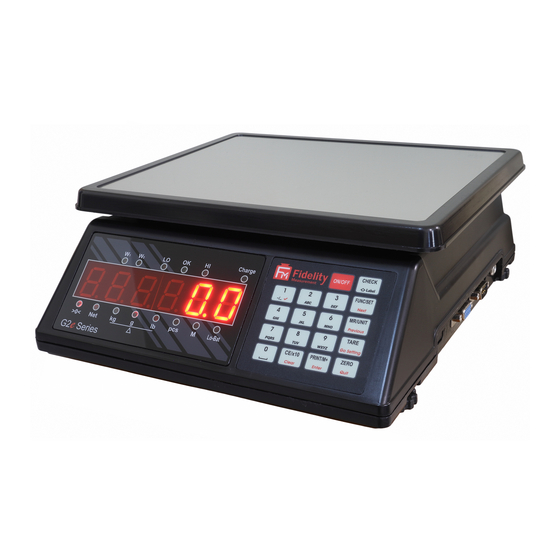
Page 9: Keys, Display & Connection Points
3. Keys, Display & Connection Points Check location of the W1 ~ Hi Indicators with actual PCB... - Page 10 Description Description Key Function during Normal Operation Key Function during Internal Function Setting [ON/OFF] Power instrument on or off. Quit without saving and power off. Starting inputting Lo and Hi limit under current checking [Check] Quick access to label settings. condition.
- Page 11 Clear value entered during setting process, or [CE/x10] Clear. Trigger the extended display mode. Numeric, letters and symbol keys. Press [0] to go to F1. [0] ~ [9] Numeric keys. Press [1] to go to F10. Press [2] to go to F10.
- Page 12 M+ Indicator Visible when memory contains of accumulated data. • Flashing: - Battery level is low. Apply power adaptor to recharge battery as soon as possible. • Lo Battery Indicator Lit on: - Battery level is at extreme low. Apply power adaptor to recharge battery immediately otherwise instrument will power off automatically shortly.
-
Page 13: Power Adaptor, Built-In Batteries And Recharging
4. Power Adaptor, Built-In Batteries and Recharging 4.1 Power Adaptor Always use the power adaptor supplied with this instrument to avoid un-recoverable damages to this instrument. 4.2 Before Plugging in Power Adaptor to Electricity Grid Double if the input voltage marked on adaptor data matches with the electricity grid. If not, do not plug in and contact your dealer immediately. -
Page 14: Internal Function Table
5.4 Internal Function Table Refer to the below tables for internal function number, parameter and setting notes. Parameters / Note Description Default = ** Press [PRINT/M+] to set offset value to zero when unloaded. Then add load on the platform to observe the span value of load applied. - Page 15 Weight Unit Enable / Disable On/Off) (On/** Off) (On/** Off) Filter & Conversion Speed ** 5 Press [FUNC/SET] or [MR/UNIT] to select: - 1 (strongest filter) for bad working environment where vibration, wind flow… etc. affect stable reading, 5 for normal environment, ...
- Page 16 Kb (keypad buzzer) St (System buzzer) Buzzer (**On/Off) (**On/Off) Check Result Buzzer & Action ** IN on Negative Value Setting procedures: - Set Check Result Buzzer then press [PRINT/M+]. Set Action on Negative Value. Check Result Buzzer oFF = Check Buzzer disabled, ...
- Page 17 Refer to operation manual for detailed setup information. Restart instrument (by power off then power on again) after F16 and/or F17 setting is changed under normal operation status. Machine ID and Group Number Machine ID Group Number Id = Machine ID number (0000~9999).
- Page 18 Near Zero value is useful for dynamic weight check applications to bypass unnecessary LO alarm during uploading and unloading process. Notes: - Value entered valid only when Check function is activated. Near zero weight value can be any value between 20d and LO limit. ...
-
Page 19: Setting Comport 1 & Comport 2
5.5 Setting Comport 1 & Comport 2 There are 2 built-in comports on this instrument: - Comport 1 is set through internal function F16. It is assigned as DTE and has a male connector. Comport 2 is set through internal function F17. It is assigned as DCE and has a female connector. Comport Pin Assignment Table Comport 1 (male) Comport 2 (female) -
Page 20: When Comport Is Set As Cmd
are available (refer to Appendix B1 and B2 for details) Press [FUNC/SET] or [MR/UNIT] until the preferred parameter appears then press [PRINT/M+] to save. 5. Instrument displays time interval (in second) between each output. 10 parameters (0, 0.5, 1.0, 1.5, 10, 30, 60, 90, 120, and 300) are available. - Page 21 • Lab 4 = Journal output format with gross and net weight of each individual transaction. This format supports weighing, piece count and ATM mode only. Refer to 5.5.3.3 for other settings. • Lab 5 = Journal output format with time and net weight of each individual transaction. This format supports weighing, piece count and ATM mode only.
-
Page 22: When Comport Is Set As Auto (Auto 1~3)
5.5.4 When comport is set as Auto (Auto 1~3) Instrument displays baud rate. 9 parameters (1200~256000) are available. Press [FUNC/SET] or [MR/UNIT] until the preferred parameter appears then press [PRINT/M+] to save. Instrument displays Parity. 3 parameters (None, odd, even) are available. Press [FUNC/SET] or [MR/UNIT] until the preferred parameter appears then press [PRINT/M+] to save. -
Page 23: Basic Operations
6. Basic Operations 6.1 Power On, Inputting Operator Number & Power Off To power on press and hold [On/Off] for 0.5 second. To power off press and hold [On/Off]. After powered on, instrument will display: - 1. Software number. 2. -
Page 24: Auto Tare (F12)
6.4.2 Auto tare (F12) 3 parameters are available: - Off, Auto and Contin a. Off: - Auto tare disable. b. Auto: - instrument will assume the first stable weight (≥ 20d or 20d1) applied is a container and will then tare off the weight of it automatically. When container is removed and gross weight result is zero, tare effect will be cancelled automatically. -
Page 25: Select The Preferred Function Mode
6.5 Select the Preferred Function Mode This instrument supports the below function modes. Abbreviation of each function mode is bracketed. • Weighing (Weigh). • Piece Count (Count). • Action-Tare-Memory (AtM). • Animal Weighing (Ani). • Quick access to Customer & Product Code Setting (PCd). Press [FUNC/SET] until the abbreviation of the desired function mode appears then press [PRINT/M+] to enter. -
Page 26: When Data Is Accumulated To Memory
6.7.3 When data is accumulated to memory 15 16 17 When a result is accumulated to memory, this instrument displays “n____x”. M+ Indicator appears to indicate that memory contains stored data. “x” means the total number of transactions accumulated to memory. -
Page 27: Enter A Customer & Product Code Manually
Cursor location of current entry is indicated by flashing. Default setting for letter entry is upper case, to change to lower case letter, press [Check]. When inputting upper case letters, OK Indicator will appear. 6.10.1 Enter a customer & product code manually 1. -
Page 28: Enter A Customer & Product Code By Scanner
6.10.2 Enter a customer & product code by scanner Default scanner input target is product code. To change scanner input target, scan either one of the below barcodes, then scan a customer or product barcode. 6.10.3 Clear a customer & product code entered To clear a customer/product code entered, press [CE/x10] for procedures 2, 3 and 4 on paragraph 6.10.1. -
Page 29: Quantity Limits Plus
• Press the preferred PLU position (numeric key 0 ~ 9), then press [PRINT/M+] to save to that PLU position and utilize these limits immediately, or • Press [PRINT/M+] to utilize these limits immediately but without saving to PLU, or •... -
Page 30: Customer / Product Code Plus
• Press the preferred PLU position (numeric key 0 ~ 9), then press [PRINT/M+] to save to that PLU position, or • Press [PRINT/M+] to utilize this preset tare immediately but without saving to PLU, or • Press [ZERO] to quit. 6.11.3.2 Recall preset tare from PLU Follow the below steps to recall preset tare value. -
Page 31: Weighing Mode
7. Weighing Mode Refer to 6.6 on how to select the desired weight unit. If zero weight cannot be obtained when unloaded, press [ZERO]. After [ZERO] is pressed, the Zero Indicator will appear Always place an object onto platform gently. Excessive force / shock applied to platform may cause un- recoverable damage to the weight sensor inside platform. -
Page 32: Piece Count Mode
8. Piece Count Mode Refer to 6.6 on how to select the desired weight unit. If a container is used, place it onto the platform and press [TARE]. Apply samples with the known quantity (sample size) on platform. Press and hold [FUNC/SET] unit numeric digits flashing then input the sample quantity through numeric keys then press [PRINT/M+]. -
Page 33: Action-Tare-Memory (Atm)
9. Action-Tare-Memory (ATM) 9.1 Description of ATM Mode It means action, then tare, then memory: - • Action = load or remove weight from weighing platform. • Tare = the above weight added on or removed from will be tare off automatically. •... -
Page 34: Animal Weighing Mode
10. Animal Weighing Mode 10.1 Description of Animal Weighing Mode Animal weighing mode is used to weigh live animals. 10.2 Basic Animal Weighing Settings Refer to 6.6 on how to select the desired weight unit. Enter Animal Weighing mode. Press and hold [FUNC/SET] to select filter. Then press [FUNC/SET] to shift between one of the below 5 parameters, then press [PRINT/M+] to confirm. -
Page 35: Static Check Function
11. Static Check Function 26 27 28 29 30 This function is used to compare current weight result with the preset LO and HI Limit. The comparison results (LO, OK, HI) will then be displayed by one of the Lo/OK/Hi indicators with or without buzzer . -
Page 36: Pc / Data Output Protocols & Formats
12. PC / Data Output Protocols & Formats 12.1 PC Output Protocols This instrument supports: - • 9 predefined PC Output Protocols. Refer to Appendix A for details. • 1 customized Output Format. Refer to Appendix B for details. 12.2 Data & Print Formats 12.2.1 Predefined output formats 5 predefined output formats (Lab1 ~ Lab 5). -
Page 37: Label Printing
14. Label Printing This instrument supports the below label printer models: - • LP50 by Datecs (www.datecs.bg/en) • TDP247, TDP345, TTP247, TTP345 by TSC (www.tscprinters.com) Notes: - • Set all preferred operation parameters and label printer model according to paragraph 8. •... -
Page 38: Quick Access To Label Settings
14.2 Quick Access to Label Settings If label printer is selected, follow the below procedures to access quick label settings during operation. At Weighing Mode, press and hold [FUNC/SET]. Instrument displays F1. Press [Check], Instrument displays number of copy (1 ~ 8) to generate each time. Press [FUNC/SET] or [MR/UNIT] until the preferred parameter appears and press [Print/M+] to save. -
Page 39: Pc Software
16. PC Software PC software (Rathohan 19 End User Program) is built to work with this instrument. This software enables users to preform: - • Real Time Operation Status Monitoring • Operation Parameters Setting • Real Time Process Monitoring • Individual and Totalized Record Storage •... -
Page 40: Built-In Batteries & Recharging
17. Built-in Batteries & Recharging 17.1 Before First Time Use To ensure the best battery performance, recharge the built-in battery for at least 8 hours before first time use. 17.2 Battery Operation Time Depends on the battery operation condition, a new and fully charged rechargeable battery can provide 50~80 operation hours. -
Page 41: Error Codes
19. Error Codes Error Description Code No. Err 1 Time value error Err 2 Date value error Err 3 Exceed manual zero Err 4 Offset out of range / unstable during power on (5 minutes for OIML and NTEP mode) Zero calibration detects offset (deadload) is too high or low. -
Page 42: Appendix A: - Pre-Defined Pc Output Protocols
Appendix A: - Pre-Defined PC Output Protocols A.1 Data Abbreviation Table Data Code Description Comma • Polarity Sign • Positive = space. Negative = minus (-) • Polarity Sign • Positive = 0. Negative = minus (-) Gross/Net • NT = Net weight •... -
Page 43: Output Formats Tables
A.2 Output Formats Tables Protocol 1 Output Format Position Data Protocol 2 Output Format Position Data Field 1 (Net Weight) Field 2 (Tare Weight) Protocol 3 Output Format Position Data Protocol 4 Output Format Position Data Protocol 5 Output Format Position Data Protocol 6 Output Format... - Page 44 Protocol 7 Output Format Position Data Protocol 8 Output Format Position Data Protocol 9 Output Format Position Data...
-
Page 45: Appendix B: - Customized Pc Output Protocol
Appendix B: - Customized PC Output Protocol This instrument supports customized PC output protocol. Under this mode: - • 2 data separation types • 7 control codes, and • 22 different transaction data are available from instrument. B.1 Customized PC Output Protocol Setting Procedures 1. -
Page 46: Customized Pc Output Content Table
B.2 Customized PC Output Content Table Symbol Explanations Nature No. of Digit Remarks CoMMA Comma Data Separator Select either one SemiCo Semi Colon Cr LF HEX Code 0D 0A HEX code 0D HEX code 0A Control Code HEX code 01 Hex code 02 Hex code 03 ... - Page 47 P Code Product Code 1 ~ 18 Blank = not entered C Code Customer Code 1~ 18 Blank = not entered Trans No. of accumulated transaction Blank = none Total Accumulated Weight Blank = none 8-digital including decimal (if any) in terms of unit.Wt Unit weight gram...
-
Page 48: Appendix C: - Lab 1 Output Formats
Appendix C: - Lab 1 Output Formats No header will be generated when line number is set = 00. See below tables for print format illustrations and explanations. C.1 Weighing, ATM & Animal Mode Illustration Date Time Tare Gross Total Ref. -
Page 49: Appendix D: - Lab 2 Standard Output Format
Appendix D: - Lab 2 Standard Output Format See below tables for print format illustrations and explanations. D.1. Weighing & ATM Mode Illustration Time 21:39:17 Time of Output Date 2020-03-28 Date of Output Accumulate Sequence No. Name Customer Code Customer Code (if entered) Pcode Product Code Product Code (if entered) -
Page 50: Animal Weighing Mode Illustration
D.3 Animal Weighing Mode Illustration Time 21:43:12 Time of Output Date 2020-03-28 Date of Output Accumulate Sequence No. Name Customer Code (if entered) Customer Code Pcode Product Code (if entered) Product Code Hold.W 2.998kg Weight Held Total 2.998kg Total Accumulated Weight... -
Page 51: Appendix E: - Customizing Lab 2 Print Format
Total_WT 20.000kg Total_QTY 2000pcs Total Accumulated Count (Note SiGn Signature Line ________________________ P Code Product Code Pcode G2e Machine ID GrouP Machine Group Number MacGp oPCodE Operator Number 8888 C CodE Customer Code Name FM Note A: This line is generated when all the below conditions are met: - a. -
Page 52: To Edit Custom Lab 2 Print Output Format
E.2 To Edit Custom Lab 2 Print Output Format Follow the below steps to create customized printout. 1. Depends on the working modes: - • Go to F21 to edit custom output for Weighing and ATM mode. Maximum 30 variants can be entered. •... -
Page 53: Appendix F: - Lab 3 Output Format
Appendix F: - Lab 3 Output Format See below tables for print format illustrations and explanations. Function & Output Weighing Count ATM Mode Animal Data 1 Operator Number Data 2 Accumulate Sequence No Data 3 Data 4 Machine ID Data 5 Machine Group Data 6 Date of Output... -
Page 54: Appendix G: - Lab 4 Output Format
ATM Mode Mode Explanation Name FM Name FM Name FM Name FM Customer Code (if entered) Product Code (if entered) Pcode G2e Pcode G2e Pcode G2e Pcode G2e Operator No (if entered) Opr 8888 Opr 8888 Opr 8888 Opr 8888... -
Page 55: Appendix H: - Lab 5 Output Format
Weighing Piece Count Animal Weighing Explanation Name FM Name FM Name FM Name FM Customer Code (if entered) Pcode G2e Pcode G2e Pcode G2e Pcode G2e Product Code (if entered) Opr 8888 Opr 8888 Opr 8888 Opr 8888 Operator No (if entered) -
Page 56: Appendix I: - Tsc Printer Installation & Setup Procedures
Appendix I: - TSC Printer Installation & Setup Procedures I.1 Get the below ready before Printer Installation An appropriate cable to connect printer and computer. This cable usually comes with the printer. If not, contact your printer supplier. Printer installation driver. This driver usually comes with the printer. If not, contact your printer supplier. Diagnostic tool for printer. -
Page 57: Appendix J: - Create & Upload Label To Tsc Printer
Appendix J: - Create & Upload Label to TSC Printer J.1 Selecting the Correct Edition for Bartender Software To enable label uploading from computer to TSC printer, it is necessary to run Bartender as Automation or Enterprise Automation edition. Procedures as below: - Install Bartender Software to computer. - Page 58 11. Double click on the preferred data source to which variant(s) has/have to add. 12. check the box below External Keyboard, then 13. enter the appropriate command on the Prompt Box (refer to paragraph K.1 for command detail). 14. Select Auto on the Source box under Template Field. 15.
-
Page 59: Appendix K: - Label Programming, Illustration & Samples
Appendix K: - Label Programming, Illustration & Samples Prompt commands, information description, working mode and suggested length on label are listed on the below table. K.1 Label Prompt Command Table Prompt Suggested Command Description Length Product Code Total accumulated pieces Machine ID Machine Group Number Operator Number... -
Page 60: Label Programming Illustration
K.2 Label programming Illustration K.3 Sample Labels Label files of the above samples (size = 50 x 80mm) with prompt commands are available for download at: - https://www.fi-measurement.com/resource/driversnsoftwares... -
Page 61: Appendix L: - Keyboard Commands
Appendix L: - Keyboard Commands Keyboard commands can be sent to this instrument from computer through any standard communication program to simulate keyboard entries. To enable keyboard commands, connect the external peripheral which generates keyboard commands to Comport 2 and set Comport 2 to CMD. Keyboard Command format as below: - Hex code 0D (CR), then Hex code 0A (LF) then Letter shown on below illustration diagram, then... -
Page 62: Appendix M: - Operation Result Reading Commands
Appendix M: - Operation Result Reading Commands Operation Result commands are those commands which are used to request operation result and details from this instrument. These commands can be sent to this instrument from computer through any standard communication program. Command format as below: - Hex code 0D (CR), then Hex code 0A (LF), then Command code listed on below command table, then... -
Page 63: Appendix N: - System Parameter & Operation Entry Setting Commands
Appendix N: - System Parameter & Operation Entry Setting Commands System parameter setting commands are used to set system parameters. Command format as below: - a. Hex code 0D (ASCII code $0D), then followed by b. Hex code 0A (LF) (ASCII code $0A) then followed by c. - Page 64 = lb: - 0 = 1; 1 = 2; 2 = 5; 3 = 10; 4 = 20; 5 = 50 = kg: - 0 = 1; 1 = 2; 2 = 5; 3 = 10; 4 = 20; 5 = 50 Division 2 of kg, g, lb ...
- Page 65 manual tare Auto power off time, = auto power off time: - 0 = Off; 1 = 1 minute; 2 = 3 minute; 3 = 5 minute; 4 = 10 minute; 5 = 20 minute display brightness, = display brightness (01 ~ 04). 01 = lowest, 04 = brightness. auto power saving, ...
- Page 66 group 1 file number, = print format: - 0 = Lab 1; 1 = Lab 2; 2 = Lab 3; 3= Lab 4; 4 = Lab 5; 5 = LP-50; 6 = TSC label format group 2 =label format group 1 file number (00~99): - 00 = file AA00; 1 = file AA01; …98 = file AA98; 99 = file AA99 ...
-
Page 67: Appendix O: - System Parameter Reading Commands
Appendix O: - System Parameter Reading Commands System parameter inquiry commands are used to check system parameter settings. Command format as below: - Hex code 0D (ASCII code $0D), then Hex code 0A (LF) (ASCII code $0A) then Command code listed on below table (all commands are case sensitive), then Hex code 20 (ASCII code $20). - Page 68 Operation Place Linearity 0 = Off; 1 = On Compensation Function ad value of zero point d1 = as value of zero point. Data length = 8 (integers only) with leading space (Hex code 20). (offset), span weight d2 = span weight value.
- Page 69 d1 = working mode: - 0 = Auto 1; 1 = Auto 2; 2 = Auto 3; 3 = Manual; 4 = PC; 5 = Scanner; 6 = Off Comport working d2 baud rate: - 0 = 1200; 1 = 2400; 2 = 4800; 3 = 9600; 4 = 19200; 5 = 38400; 6 = 57600; 7 = 115200; 8 = 256000 ...
- Page 70 Machine ID & group d1 = 4 digit machine ID number. Nothing = no machine ID is set number d2 = 2-digit machine group number. Nothing = no group number is set 4-digit operator number. **** = no operator number is set Operator Number Customer Code 1~18 actual digit of Customer Code set.
- Page 71 Fidelity Measurement Co., Ltd. www.fi-measurement.com e-mail: info@fi-measurement.com...
Need help?
Do you have a question about the G2e and is the answer not in the manual?
Questions and answers