
Related Manuals for SCHUNK FTD


Summary of Contents for SCHUNK FTD
- Page 1 Translation of original commissioning instructions Commissioning instructions Force-torque sensor system...
- Page 2 Imprint Imprint Copyright: This manual is protected by copyright. The author is SCHUNK GmbH & Co. KG. All rights reserved. Technical changes: We reserve the right to make alterations for the purpose of technical improvement. Document number: 389627 Version: 01.00 | 07/04/2021 | en...
-
Page 3: Table Of Contents
Available software interfaces and demo programs.......... 41 Manual calculations.................... 42 Creating your own application ................ 42 Troubleshooting ..................... 43 Saturation ...................... 43 Signal noise...................... 43 Measurement data deviation / drift.............. 43 Hysteresis ...................... 43 01.00 | FTD | Commissioning instructions | en | 389627... - Page 4 Table of Contents Maintenance ...................... 44 EU Declaration of Conformity ................. 45 10 Appendix ........................ 46 10.1 .......................... 46 01.00 | FTD | Commissioning instructions | en | 389627...
-
Page 5: General
WARNING Dangers for persons! Non-observance can lead to irreversible injury and even death. CAUTION Dangers for persons! Non-observance can cause minor injuries. CAUTION Material damage! Information about avoiding material damage. 01.00 | FTD | Commissioning instructions | en | 389627... -
Page 6: Applicable Documents
• Catalog data sheet of the purchased product * • Assembly and operating manual of the sensor * • Help files for FTD DAQ software (ATI DAQ F/T software) ** The documents marked with an asterisk (*) can be downloaded on our homepage schunk.com The documents labeled with an asterisk (**) can be downloaded from schunk.com/ft-downloads. -
Page 7: Basic Safety Notes
Use of unauthorized spare parts Using unauthorized spare parts can endanger personnel and damage the product or cause it to malfunction. • Use only original spare parts or spares authorized by SCHUNK. 2.5 Personnel qualification Inadequate qualifications of the personnel... -
Page 8: Disposal
Only qualified electricians may perform electrical installations. • Check if de-energized, ground it and hot-wire. • Cover live parts. • 01.00 | FTD | Commissioning instructions | en | 389627... -
Page 9: Technical Data
Dimensions and max. loads on the force-torque sensor Detailed information on the mounting, installation and maintenance of the sensor is provided in the Assembly and Operating Manual for the sensor, Applicable documents 6]. 01.00 | FTD | Commissioning instructions | en | 389627... -
Page 10: Calculating The Forces And Moments
Open Temperature compensation is Copy UserAxis calibration matrix calibration file from FTxxx.cal and copy it to the normally not required. FTxxx.cal runtime matrix Calculating the forces and moments 01.00 | FTD | Commissioning instructions | en | 389627... - Page 11 Correction value of The correction value of the customer-provided amplifier is only the customer- required if an additional amplifier is used. The factor provided amplifier compensates for the entire calculation. 01.00 | FTD | Commissioning instructions | en | 389627...
-
Page 12: Design And Description
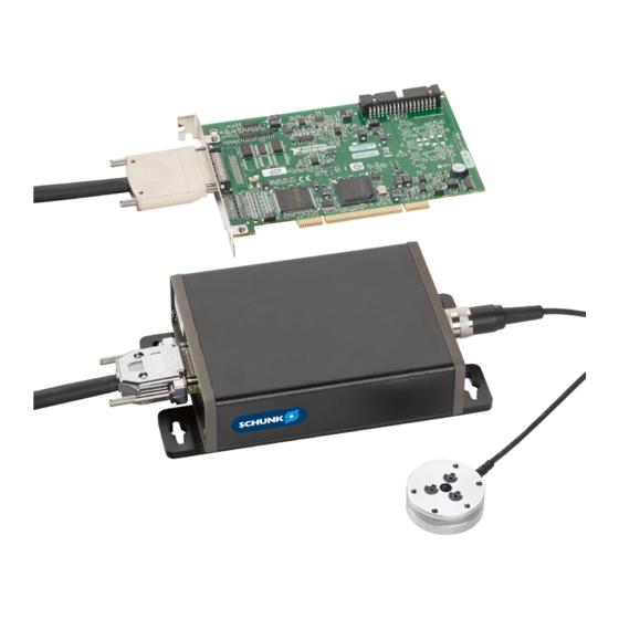
Top: Force-torque sensor with interface electronics (from gamma and larger) / Bottom: Force-torque sensor with sensor cable (Nano and Mini) Sensor cable connection Integrated sensor cable Tool side adapter plate Robot side adapter plate 01.00 | FTD | Commissioning instructions | en | 389627... - Page 13 12 V power supply unit is automatically selected. Power supply box for nano / mini force-torque sensors with integrated sensor electronics 12-pin socket, sensor cable connection 26-pin connector, DAQ cable connection Power supply unit 12 V 01.00 | FTD | Commissioning instructions | en | 389627...
- Page 14 DAQ cable from PS box / IFPS box to customer-provided data acquisition card Unterminated cable ends 68-pin connector (type D) for customer-provided data acquisition card 26-pin connector, PS box / IFPS box connection 01.00 | FTD | Commissioning instructions | en | 389627...
- Page 15 DAQ cable from IFPSMC box to customer-provided data acquisition card 68-pin connector (VHDCI), customer-provided data acquisition card connection 68-pin connector (type D), customer-provided data acquisition card connection 68-pin connector (type D), IFPSMC box connection 01.00 | FTD | Commissioning instructions | en | 389627...
- Page 16 Earth Power supply Data collection USB data acquisition (DAQ) device with screw terminal connections USB data acquisition (DAQ) device PCI DAQ card PCI DAQ card Terminal block with BNC inputs 01.00 | FTD | Commissioning instructions | en | 389627...
-
Page 17: Description
Afterwards, the software (provided by the customer) uses the calibration matrix to graphically display the occurring forces and torques on the PC if required. 01.00 | FTD | Commissioning instructions | en | 389627... -
Page 18: Assembly And Installation
2. Optional: Install the software, Installing the software 39]. 3. Check for functionality. 4. Mount the force-torque sensor on the robot, see the installation and operating instructions for the sensor. 01.00 | FTD | Commissioning instructions | en | 389627... -
Page 19: Electrical Connection
4. Connect power supply unit 12 V (3) to power supply box (4). 5. For FT sensors starting from gamma and larger: Connect sensor cable (5) to force-torque sensor (6). 6. Connect sensor cable (5) to power supply box (4). 7. Check for functionality. 01.00 | FTD | Commissioning instructions | en | 389627... - Page 20 6. Connect sensor cable (5) to IFPSMC box (4). The serial number of the sensor must match the serial number on the connector on the IFPSMC box. 7. Check for functionality. 01.00 | FTD | Commissioning instructions | en | 389627...
- Page 21 4. Connect power supply unit 12 V (4) to power supply box (5). 5. For FT sensors starting from gamma and larger: Connect sensor cable (5) to force-torque sensor (6). 6. Connect sensor cable (6) to power supply box (5). 7. Check for functionality. 01.00 | FTD | Commissioning instructions | en | 389627...
- Page 22 7. Connect sensor cable (7) to IFPS box (5). The serial number of the sensor must match the serial number on the socket on the IFPSMC box. 8. Check for functionality. 01.00 | FTD | Commissioning instructions | en | 389627...
- Page 23 5. Connect power supply unit 12 V (4) to power supply box (5). 6. For FT sensors starting from gamma and larger: Connect sensor cable (5) to force-torque sensor (6). 7. Connect sensor cable (6) to power supply box (5). 8. Check for functionality. 01.00 | FTD | Commissioning instructions | en | 389627...
- Page 24 Violet (AI 4) (AI 20) output Violet / White (AI 12) (AI 28) reference Grey (AI 5) (AI 21) output Grey / White (AI 13) (AI 29) reference T out T ref reserved 01.00 | FTD | Commissioning instructions | en | 389627...
- Page 25 IFPS box (NI) without IP with IP acquisition connector reserved FTD-C-PS- V68 cable reserved FTD-C-PS- NI cable reserved Stripping Stripping Stripping Stripping Shielding Shielding D Gnd D Gnd (twisted pair) 01.00 | FTD | Commissioning instructions | en | 389627...
-
Page 26: Force-Torque Sensor
-VANA power input Yellow / White SG1 reference Violet SG4 output White T out Black / White reserved Orange / White reserved Green SG2 output Violet / White SG4 reference White / Black T ref Green / White SG2 reference Stripping Stripping Shielding Shield 01.00 | FTD | Commissioning instructions | en | 389627... - Page 27 Signal Minimum Normal Maximum operation power input voltage [VDC] power input voltage [VDC] power input current [mA] power input current [mA] power input noise [mV p-p] power input regulation [%] 01.00 | FTD | Commissioning instructions | en | 389627...
-
Page 28: Ps / Ifps Box
Red / White DGnd White / Black T ref Grey / White SG5 reference Violet / White SG4 reference Blue / White SG3 reference Green / White SG2 reference Yellow / White SG1 reference Brown / White SG0 reference Black / White DIO0 Black AIGnd Stripping Shielding Stripping 01.00 | FTD | Commissioning instructions | en | 389627... - Page 29 13, 12 White / Black T ref Grey / White SG5 reference Violet / White SG4 reference Blue / White SG3 reference Green / White SG2 reference Yellow / White SG1 reference Brown / White SG0 reference Black / White DIO0 Black AIGnd Stripping Shielding Stripping 01.00 | FTD | Commissioning instructions | en | 389627...
- Page 30 Note: Shown here is the 5V power supply via the DAQ cable. Alternatively, the 5V power supply data acquisition power supply can also be supplied by the 12V power supply unit provided. Can be connected to customer-provided data acquisition card (differential) 01.00 | FTD | Commissioning instructions | en | 389627...
- Page 31 Note: Shown here is the 5V power supply via the DAQ cable. Alternatively, the 5V power supply power supply can also be supplied by the 12V power supply unit provided. data acquisition Can be connected to customer-provided data acquisition card (single-ended) 01.00 | FTD | Commissioning instructions | en | 389627...
- Page 32 No connection AI SENSE 55 n.c. No connection AI GND 24 Violet SG4 output AI 4 56 Violet SG4 output AI 20 25 Violet / White SG4 reference AI 12 57 Violet / White SG4 reference AI 28 01.00 | FTD | Commissioning instructions | en | 389627...
- Page 33 62 n.c. No connection AI 30 31 n.c. No connection AI 7 63 n.c. No connection AI 23 32 n.c. No connection AI 15 64 n.c. No connection AI 31 01.00 | FTD | Commissioning instructions | en | 389627...
-
Page 34: Ifpsmc Box
1 / 23 1 / 57 AI 36 AI 36 AI 44 1 / 55 1 / 21 AI 37 AI 37 AI 45 1 / 20 1 / 54 01.00 | FTD | Commissioning instructions | en | 389627... - Page 35 1 / 2 AI 71 AI 71 AI 79 1 / 1 1 / 35 The available signals on the IFPSMC box are shown in the appendix of this manual, Appendix 46]. 01.00 | FTD | Commissioning instructions | en | 389627...
- Page 36 Assembly and installation Connections DAQ cable for IFPSMC box (SHC-68-68-EPM) 68-pin connector (VHDCI), customer-provided data acquisition card connection 68-pin connector (type D), IFPSMC box connection 01.00 | FTD | Commissioning instructions | en | 389627...
- Page 37 Red / White Shielding 3 White / Orange Orange / White Shielding 4 White / Green Green / White Shielding 5 White / Blue Blue / White Shielding 6 White / Violet Violet / White Shielding 7 White / Grey Grey / White Shielding 8 Brown / Black Black / Brown Red / Black Black / Red White / Yellow Red / Blue shielded 01.00 | FTD | Commissioning instructions | en | 389627...
- Page 38 Current flow at room temperature Designation Input current [A] 5VDC 12VDC 15VDC 9105-IFPSMC-2 0.36 0.19 0.16 9105-IFPSMC-3 0.54 0.28 0.24 9105-IFPSMC-4 0.72 0.37 0.32 9105-IFPSMC-5 0.90 0.46 0.40 9105-IFPSMC-6 1.08 0.56 0.48 01.00 | FTD | Commissioning instructions | en | 389627...
-
Page 39: Installing The Software
✓ 2. In the navigation, click on File > Load Calibration and open the unzipped FTxxxx.cal file. Bar graphs for the measured forces and the measured ✓ torques are displayed. 01.00 | FTD | Commissioning instructions | en | 389627... - Page 40 Left: Load within the range of measurement, right: Load outside the permissible range of measurement 6. When the sensor has been successfully mounted, select "Resolved F/T Data" in the "Data Type" box. The force-torque sensor system is ready for use. ✔ 01.00 | FTD | Commissioning instructions | en | 389627...
-
Page 41: Operation
Microsoft Visual Basic 6.0 source. • LabVIEW Sample: This demo program in LabVIEW uses the ATI DAQ FT automation application and analog input provided by National Instrument devices to represent forces and moments. 01.00 | FTD | Commissioning instructions | en | 389627... -
Page 42: Manual Calculations
• ATI DAQ FT components or C library: For Windows, SCHUNK recommends the ATI DAQ FT. In some cases ATI DAQ FT cannot be used, e.g. if ActiveX is not supported. In these cases, ATI DAQ FT can assist in the installation of the sensor, but does not have to be part of the final application. -
Page 43: Troubleshooting
7.4 Hysteresis Possible cause Corrective action Measured values are not completely reset Operate all components separately. after loading and unloading. Thoroughly clean the sensor body and adapter plate of contamination. 01.00 | FTD | Commissioning instructions | en | 389627... - Page 44 Check all parts for damage and wear. annual Send sensor and power supply box to SCHUNK for calibration. Send sensors and IFPSMC box to SCHUNK for calibration. as required Send damaged products to SCHUNK for repair. 01.00 | FTD | Commissioning instructions | en | 389627...
- Page 45 Directive 2014/30/EU and will be made available to national authorities on demand. The signatory is resident at the manufacturer's address and is authorized to compile this documentation. Signed for and on behalf of: SCHUNK GmbH & Co. KG Dr.-Ing. Manuel Baumeister, Technology & Innovation, Mechatronics &...
- Page 46 Available(-) Notes: TC-SGx(x) = Transducer Connection number - Signal (SGx) - positive (+) or negative (-) input Available (x) = User signal available - positive (+) or negative (-) input 01.00 | FTD | Commissioning instructions | en | 389627...
- Page 47 Available(+) Notes: TC-SGx(x) = Transducer Connection number - Signal (SGx) - positive (+) or negative (-) input Available (x) = User signal available - positive (+) or negative (-) input 01.00 | FTD | Commissioning instructions | en | 389627...
- Page 48 TC1-SG4(-) Notes: TC-SGx(x) = Transducer Connection number - Signal (SGx) - positive (+) or negative (-) input Available (x) = User signal available - positive (+) or negative (-) input 01.00 | FTD | Commissioning instructions | en | 389627...
- Page 49 TC1-SG4(+) Notes: TC-SGx(x) = Transducer Connection number - Signal (SGx) - positive (+) or negative (-) input Available (x) = User signal available - positive (+) or negative (-) input 01.00 | FTD | Commissioning instructions | en | 389627...
- Page 52 Translation of original commissioning instructions SCHUNK GmbH & Co. KG Clamping and gripping technology Bahnhofstr. 106 - 134 D-74348 Lauffen/Neckar Tel. +49-7133-103-0 Fax +49-7133-103-2399 info@de.schunk.com schunk.com Folgen Sie uns I Follow us...
Need help?
Do you have a question about the FTD and is the answer not in the manual?
Questions and answers