Advertisement
Available languages
Available languages
Quick Links
Advertisement

Related Manuals for BS 20 A Series


Summary of Contents for BS 20 A Series
- Page 1 Bedienungsanleitung Instruction Manual 20er A/Q-Serie 20 A/Q-Series...
-
Page 2: Table Of Contents
Inhalt/Contents Produktbeschreibung ���������������������������� 3 Technische Daten ������������������������������������ 4 Montageanleitung ����������������������������������� 5 Gebrauchshinweise ������������������������������ 13 Product description ������������������������������������ 3 Technical data ����������������������������������������������� 4 Assembly instructions ������������������������������� 9 Instructions for use ���������������������������������� 13... -
Page 3: Produktbeschreibung
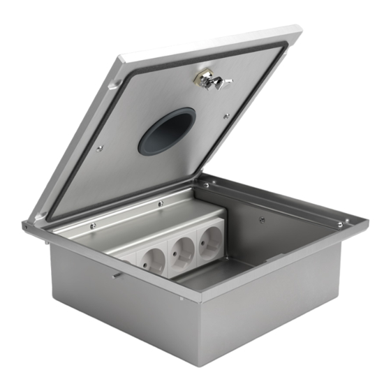
20er A-Serie/Q-Serie 20 A-Series/Q-Series Exemplarisch ist der Bodentank 2003A The 2003A floor tank is shown as an abgebildet. Das Montageprinzip gilt für alle example� The installation principle applies Bodentanks der 20er A-Serie: 2003A, 2004A, to all floor tanks from the 20 A-Series: 2008A und der 20er Q-Serie: 2003Q, 2004Q, 2003A, 2004A, 2008A and the 20 Q-Series: 2008Q. -
Page 4: Technische Daten
Technische Daten/Technical specifications Art.-Nr. 2003A 2004A 2008A Item No Einbaumaße 200 x 203 x 92 mm 250 x 253 x 92 mm 250 x 253 x 92 mm Instl dim Zuleitungen 2 hinten/back 4 hinten/back 8 seitlich/lateral Supply line Ø 25 mm Ø... -
Page 5: Montageanleitung
Montageanleitung Schritt 1 Schritt 2 Den Deckel abschrauben� Anschließend Vor dem Gießen des Estrichs einen den Geräteträger von dem Gehäuse Polystyrol-Block (PB), der in seiner äußeren demontieren� Abmessung umlaufend ca� 40 mm größer ist als die Dose*, als Platzhalter auf die ausgelegte Dämmschicht (P) kleben�... - Page 6 Schritt 3 Nach dem Gießen des Estrichs den Polystyrol-Block (PB) aus dem Estrich entfernen� Das Gehäuse nun in die entstandene Bodenaussparung auf ein Mörtelbett* (M) einsetzen und die Leerrohre in die Öffnungen des Gehäuses einführen� *Achtung! Die Höhe des Mörtelbetts muss so vermessen werden, dass der Abstand ’t’...
- Page 7 Schritt 4 Das Gehäuse abdichten� (Tipp: die Gehäuseöffnung beispielsweise mit Pappe abdecken, wie abgebildet.) Die Aussparung um das Gehäuse nun mit Mörtel (M) auffüllen� Die Position des Gehäuses vor dem Aushärten des Mörtels mit der Wasserwaage (W) überprüfen!
- Page 8 Schritt 5 Nach dem Aushärten die Steckdosen anschließen, den Geräteträger wieder in das Gehäuse einschrauben, sowie den Deckel an den Rahmen � Danach erst den Belag (B) im Raum verlegen� Der Bodentank ist nun erfolgreich eingebaut� (Siehe Querschnitt unten)
-
Page 9: Assembly Instructions
Assembly Instructions Step 1 (Preparations) Step 2 Unscrew the lid � Then remove the device Before pouring the screed, a polystyrene carrier from the housing � block (PB) with a circumference of approx� 40 mm larger than the box in its outer dimension* must be glued to the insulation layer (P) as a placeholder�... - Page 10 Step 3 Remove the polystyrene block (PB) after pouring the screed� Now insert the housing into the resulting floor recess on a mortar bed* (M) and install the conduits into the openings of the housing � *Attention! The height of the mortar bed must be measured so that the distance ’t’...
- Page 11 Step 4 Seal the housing � (Tip: cover the box ope- ning, for example, with cardboard, as shown.) Now fill the recess around the housing with mortar (M)� Check the position of the housing with the spirit level (W) before curing the mortar!
- Page 12 Step 5 After curing, connect the sockets, screw the device carrier back into the housing and screw the lid onto the frame � Lay the remaining covering (B) in the room� The floor socket is now successfully installed� (See cross section below.)
-
Page 13: Gebrauchshinweise
Gebrauchshinweise/Instructions for use Um eine anhaltende Funktion des Bodentanks zu In order to ensure a lasting function of the gewährleisten sind folgende Hinweise zu beachten: floor socket, the following instructions must be observed: • Anschluss, Reparatur oder Instandhaltung sind von einer ausgebildeten Fachkraft durchzuführen�... - Page 14 © by BS Bodensteckdosen Systemtechnik GmbH BS Bodensteckdosen Systemtechnik GmbH Dingerdisser Str� 36 33699 Bielefeld, Germany Tel +49 521 9892780 Fax +49 521 989278-30 info@bodensteckdosen�com www�bodensteckdosen�com Irrtümer und technische Änderungen vorbehalten. Subject to errors and technical changes.
Need help?
Do you have a question about the 20 A Series and is the answer not in the manual?
Questions and answers