Advertisement
Available languages
Available languages
Quick Links
Advertisement

Related Manuals for BS 89 H Series


Summary of Contents for BS 89 H Series
- Page 1 Bedienungsanleitung Instruction Manual 89er H-Serie 89 H-Series...
-
Page 2: Table Of Contents
Inhalt/Contents Produktbeschreibung ���������������������������� 3 Technische Daten ������������������������������������ 4 Montageanleitung ����������������������������������� 5 Gebrauchshinweise ������������������������������ 21 Product description ������������������������������������ 3 Technical data ����������������������������������������������� 4 Assembly instructions ����������������������������� 13 Instructions for use ���������������������������������� 21... -
Page 3: Produktbeschreibung
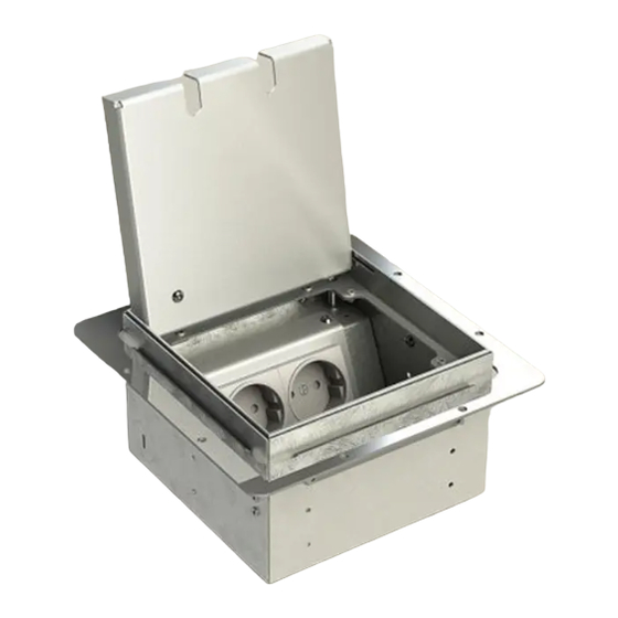
89er H-Serie/89 H-series Exemplarisch ist die Bodensteckdose 8902H abgebildet. Das Montageprinzip gilt für alle Bodensteckdosen der 89er H-Serie: 8902H, 8903H, 8904H, 8906H, 8908H. The floor socket 8902H is shown as an example� The installation principle applies to all floor sockets from the 89 H-series: 8902H, 8903H, 8904H, 8906H, 8908H� Bezeichnung/Designation (B) Belag/Flooring ... -
Page 4: Technische Daten
Technische Daten/Technical specifications Artikel-Nr. 8902H 8904H 8908H Item No Einbaumaße 167 x 167 x 103 mm 217 x 167 x 103 mm 217 x 217 x 103 mm Instl dim 4 x vorne/front, 2 x seitlich/lateral, 2 x seitlich/lateral, 4 x seitlich/lateral, Zuleitungen 2 x hinten/back, 2 x hinten/back,... -
Page 5: Montageanleitung
Montageanleitung Schritt 1 Schritt 2 (Vorbereitungen) Den Deckel abnehmen und den An gewünschter Position einen Ausschnitt den Geräteträger von der Box in der Größe der Box -Außenmaße in den abmontieren� Hohlboden (H) sägen/schneiden�... - Page 6 Schritt 3 Leitungen/Leerohre (L) oder Kabelkanal bis zur Dose verlegen und Geräte anschließen�...
- Page 7 Schritt 4 Dose einsetzen und den Unterbaurahmen Achtung: Der Unterbaurahmen kann in drei verschiedenen Höhen an der Box am Hohlboden (H) verschrauben� montiert werden (siehe Querschnitte S. 12)�...
- Page 8 Schritt 5 Das Gehäuse abdichten� (Tipp: Das Estrich (E) eingießen� Bei einer Montage ohne Estrich auf dem Hohlboden weiter Gehäuse abkleben und die Gehäuse- ab Schritt 6 (→ siehe auch Querschnitt öffnung, wie abgebildet, beispielsweise mit Styrodur abdecken). Nun die Dose mit Abb.
- Page 9 Achtung! Sollte die Höhe des Estrichs (E), oder des Bodenbelags niedriger ausfallen als die Höhe der Bodensteckdose (unter 100 mm), können die perforierten Laschen an der oberen Box- kante herausgebrochen werden�...
- Page 10 Schritt 6 Den Bodenbelag (B) im Raum verlegen und den Deckel mit Belag auskleben�...
- Page 11 Schritt 7 Mithilfe der Nivellierschrauben die Boden- steckdose bündig mit dem Belag (B) setzen�...
- Page 12 Ansicht im Querschnitt mit herausgebrochenen Laschen. (B) Belag, (E) Estrich, (H) Hohlboden. Abb. 1 (mit Estrich) Stütze Fundament Abb. 2 (ohne Estrich)
-
Page 13: Assembly Instructions
Assembly Instructions Step 1 (preparations) Step 2 Remove the lid and dismantle Saw/cut a cutout in the size of the the device carrier from the housing � housing outer dimensions into the hollow floor (H) at the desired position�... - Page 14 Step 3 Lay cables/conduits (L) up to the housing and connect devices�...
- Page 15 Step 4 The base frame can be Attention: Insert the floor socket and screw the base frame on the hollow floor (H)� mounted at three different heights on the housing (see cross-section page 20)�...
- Page 16 Step 5 Seal the housing � (Tip: Mask the housing If installing without screed on the hollow floor, continue from step 6 (→ see also and cover the housing opening with Styrodur for example, as shown). Now pour cross-section Fig. 2, page 20). the outside of the housing ...
- Page 17 Attention! If the height of the screed (E), or the floor covering is lower than the height of the floor socket (less than 100 mm), the perforated tabs on the top box edge can be broken out�...
- Page 18 Step 6 Lay the floor covering (B) in the room� Glue floor cover into the lid �...
- Page 19 Step 7 Use the leveling screws to put the floor socket flush with the floor covering (B)�...
- Page 20 Cross-sectional view with tabs broken out. (B) covering, (E) screed, (H) hollow floor. Fig. 1 (with screed) Pillar Base Fig. 2 (without screed)
-
Page 21: Gebrauchshinweise
Gebrauchshinweise/Instructions for use Um eine anhaltende Funktion der In order to ensure a lasting function of the Bodensteckdose zu gewährleisten sind folgende floor socket, the following instructions must Hinweise zu beachten: be observed: • Der Anschluss, die Reparatur oder die •... - Page 22 © by BS Bodensteckdosen Systemtechnik GmbH BS Bodensteckdosen Systemtechnik GmbH Oldermanns Hof 2a 33719 Bielefeld Tel +49 521 260109-90 Fax +49 521 260109-99 info@bodensteckdosen�com www�bodensteckdosen�com Irrtümer und technische Änderungen vorbehalten Errors and technical changes reserved.
Need help?
Do you have a question about the 89 H Series and is the answer not in the manual?
Questions and answers